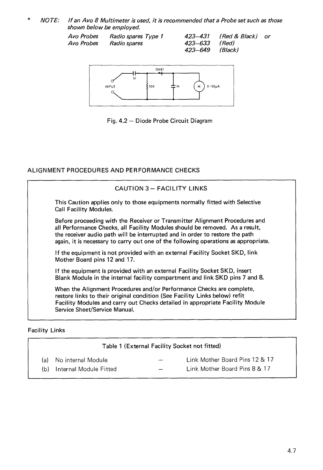
0 -50pA
II
I
.1
n
INPUT
f 101(
T
1n
0A91
NOTE: If an Avo 8 Multimeter is used, it is recommended that a Probe set such as those
shown below be employed.
Avo Probes Radio spares Type 1
423-431 (Red & Black) or
Avo Probes Radio spares
423-633 (Red)
423-649 (Black)
Fig. 4.2 — Diode Probe Circuit Diagram
ALIGNMENT PROCEDURES AND PERFORMANCE CHECKS
CAUTION 3— FACILITY LINKS
This Caution applies only to those equipments normally fitted with Selective
Call Facility Modules.
Before proceeding with the Receiver or Transmitter Alignment Procedures and
all Performance Checks, all Facility Modules should be removed. As a result,
the receiver audio path will be interrupted and in order to restore the path
again, it is necessary to carry out one of the following operations as appropriate.
If the equipment is not provided with an external Facility Socket SKD, link
Mother Board pins 12 and 17.
If the equipment is provided with an external Facility Socket SKD, insert
Blank Module in the internal facility compartment and link SKD pins 7 and 8.
When the Alignment Procedures and/or Performance Checks are complete,
restore links to their original condition (See Facility Links below) refit
Facility Modules and carry out Checks detailed in appropriate Facility Module
Service Sheet/Service Manual.
Facility Links
Table 1 (External Facility Socket not fitted)
(a)
No internal Module
—
Link Mother Board Pins 12 & 17
(b)
Internal Module Fitted
Link Mother Board Pins 8 & 17
4.7