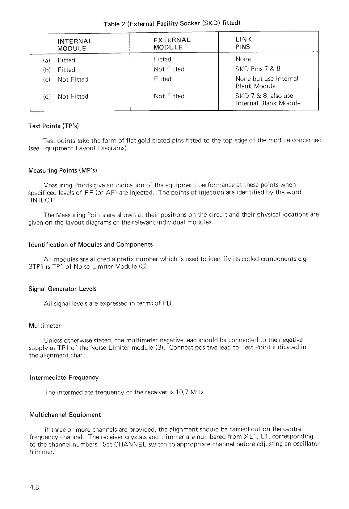
Table 2 (External Facility Socket (SKD) fitted)
INTERNAL
MODULE
EXTERNAL
MODULE
LINK
PINS
(a)
Fitted
(b)
Fitted
(c)
Not Fitted
(d)
Not Fitted
Fitted
Not Fitted
Fitted
Not Fitted
None
SKD Pins 7 & 8
None but use Internal
Blank Module
SKD 7 & 8; also use
Internal Blank Module
Test Points (TP's)
Test points take the form of flat gold plated pins fitted to the top edge of the module concerned
(see Equipment Layout Diagrams).
Measuring Points (MP's)
Measuring Points give an indication of the equipment performance at these points when
specificed levels of BF (or AF) are injected. The points of injection are identified by the word
'INJECT'.
The Measuring Points are shown at their positions on the circuit and their physical locations are
given on the layout diagrams of the relevant individual modules.
Identification of Modules and Components
All modules are alloted a prefix number which is used to identify its coded components e.g.
3TP1 is TP1 of Noise Limiter Module (3).
Signal Generator Levels
All signal levels are expressed in terms of PD.
Multinneter
Unless otherwise stated, the multi meter negative lead should be connected to the negative
supply at TP1 of the Noise Limiter module (3). Connect positive lead to Test Point indicated in
the alignment chart.
Intermediate Frequency
The intermediate frequency of the receiver is 10,7 MHz
Multichannel Equipment
If three or more channels are provided, the alignment should be carried out on the centre
frequency channel. The receiver crystals and trimmer are numbered from XL1, L1, corresponding
to the channel numbers. Set CHANNEL switch to appropriate channel before adjusting an oscillator
trimmer.
4.8