0
0
L
T'
N -OUTPUT
RED
__BLACK
TNC-INPUT
0
BROWN
BLUE
YELLOW/GREEN
BELE
BROWN
YELLOW/GREEN
•
•
0
•
0 0
5A
O
O
12A
0
0
0
0
12V
0
NEGATIVE GROUND
0
NOTE
SWITCHING LINE SHOWN IN DOTTED LINE
12V
0
POSITIVE GROUND
FLOATING GROUND
A200
M201
A200
0
O
0
0
0
M201
12A
5A
12A
5A
0
12V
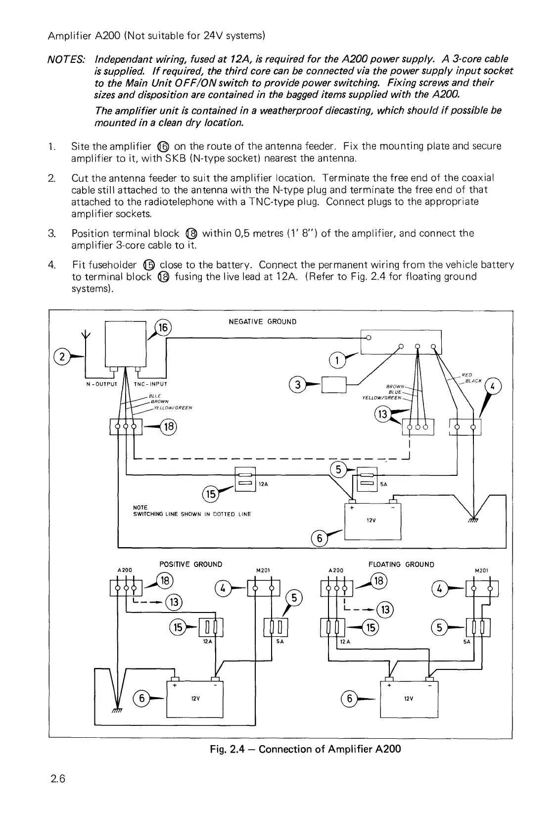
Amplifier A200 (Not suitable for 24V systems)
NOTES: Independant wiring, fused at 12A, is required for the A200 power supply. A 3-core cable
is supplied. If required, the third core can be connected via the power supply input socket
to the Main Unit OFF/ON switch to provide power switching. Fixing screws and their
sizes and disposition are contained in the bagged items supplied with the A200.
The amplifier unit is contained in a weatherproof diecasting, which should if possible be
mounted in a clean dry location.
1.
Site the amplifier
on the route of the antenna feeder. Fix the mounting plate and secure
amplifier to it, with SKB (N-type socket) nearest the antenna.
2.
Cut the antenna feeder to suit the amplifier location. Terminate the free end of the coaxial
cable still attached to the antenna with the N-type plug and terminate the free end of that
attached to the radiotelephone with a TNC-type plug. Connect plugs to the appropriate
amplifier sockets.
3.
Position terminal block (3 within 0,5 metres (1' 8") of the amplifier, and connect the
amplifier 3-core cable to it.
4.
Fit fuseholder
close to the battery. Connect the permanent wiring from the vehicle battery
to terminal block
fusing the live lead at 12A. (Refer to Fig. 2.4 for floating ground
systems).
Fig. 2.4 — Connection of Amplifier A200
2.6