TYPE TNC
E
-
]
CUT ANTENNA
FEEDER TO SUIT
POSITION OF A200
00 0
CONNECT ANTENNA PLUGS SUPPLIED WITH A200
TYPE N
lb
]=,
TYPE TNC
-
9 5mm
SOLDER SECURELY HERE
SOLDER SECURELY HERE
El
7mm
CLAMP PLAIN
FERRULE REAR
MALE
NUT GASKET
INSULATOR CONTACT
0 4mm
PLUG BODY
EMI
0 4mm
01/1611,93
felAffi /Ai
°
Z4I
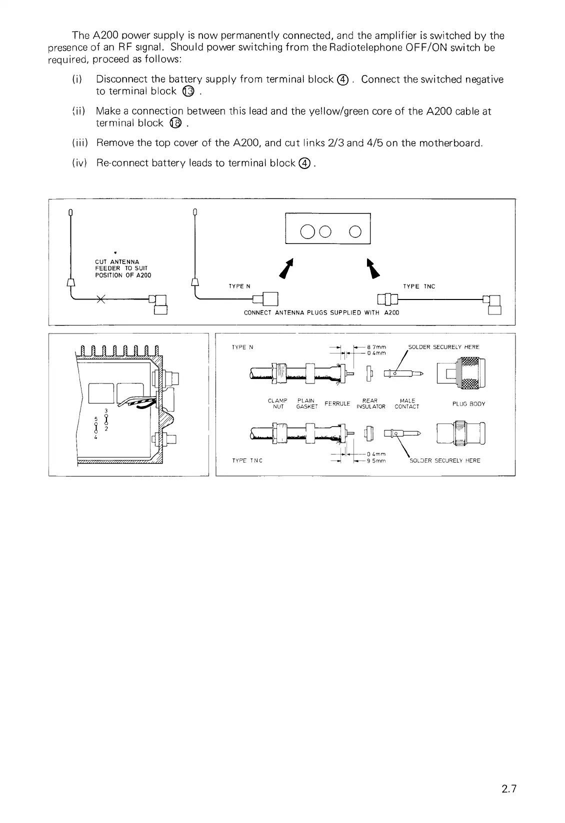
The A200 power supply is now permanently connected, and the amplifier is switched by the
presence of an RF signal. Should power switching from the Radiotelephone OFF/ON switch be
required, proceed as follows:
(i)
Disconnect the battery supply from terminal block ® . Connect the switched negative
to terminal block 0 .
(ii)
Make a connection between this lead and the yellow/green core of the A200 cable at
terminal block
(iii)
Remove the top cover of the A200, and cut links 2/3 and
4
/
5
on the motherboard.
(iv)
Re-connect battery leads to terminal block 0 .
2.7