8
*L1 or
18
Ln
5
L1
5
L2
5
L3
1
L8
5
L1 , L2, L3
1
L1, L2, L3
L4, L5, L6
t L7, L8
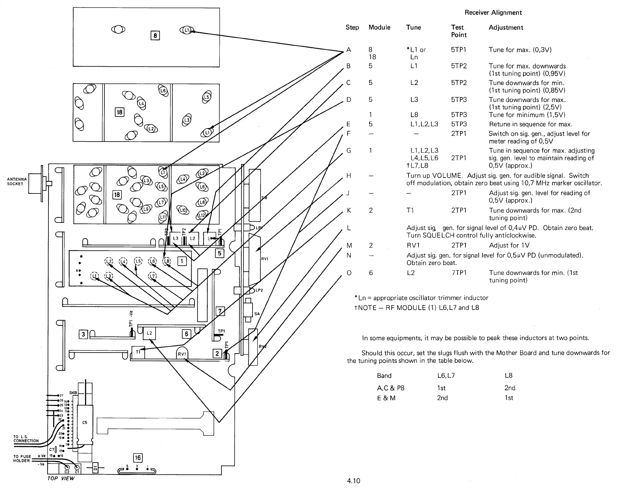
2TP1
Switch on sig. gen., adjust level for
meter reading of 0,5V
Tune in sequence for max. adjusting
2TP1
sig. gen. level to maintain reading of
0,5V (approx.)
Step Module Tune
Test
Adjustment
Point
5TP1
Tune for max. (0,3V)
5TP2
Tune for max. downwards
(1st tuning point) (0,95V)
5TP2
Tune downwards for min.
(1st tuning point) (0,85V)
5TP3
Tune downwards for max.
(1st tuning point) (2,5V)
5TP3
Tune for minimum (1,5V)
5TP3
Retune in sequence for max.
L8
2nd
1st
A,C & P8
E & M
Band
L6,L7
1st
2nd
Receiver Alignment
Turn up VOLUME. Adjust sig. gen. for audible signal. Switch
off modulation, obtain zero beat using 10,7 MHz marker oscillator.
2TP1
Adjust sig. gen. level for reading of
0,5V (approx.)
2
Ti
2TP1
Tune downwards for max. (2nd
tuning point)
Adjust sig. gen. for signal level of 0,4uV PD. Obtain zero beat.
Turn SQUELCH control fully anticlockwise.
2
RV1
2TP1
Adjust for 1V
Adjust sig. gen. for signal level for 0,51A/ PD (unmodulated).
Obtain zero beat.
6
L2
7TP1
Tune downwards for min. (1st
tuning point)
*Ln = appropriate oscillator trimmer inductor
tNOTE — RF MODULE (1) L6, L7 and L8
4.10
0
ANTENNA
SOCKET
SKB
27
••••
,
..y26 14.
••••25
1
30
120
=24 110
23
•
•
•
20•
TO L.S.
CONNECTION
190 •
•
n
leo
l
•
C7
0
17•
TO FUSE +Ve
• 516
HOLDER
- Ve
(7)
C2 Cl
TOP VIEW
In some equipments, it may be possible to peak these inductors at two points.
Should this occur, set the slugs flush with the Mother Board and tune downwards for
the tuning points shown in the table below.