QC)
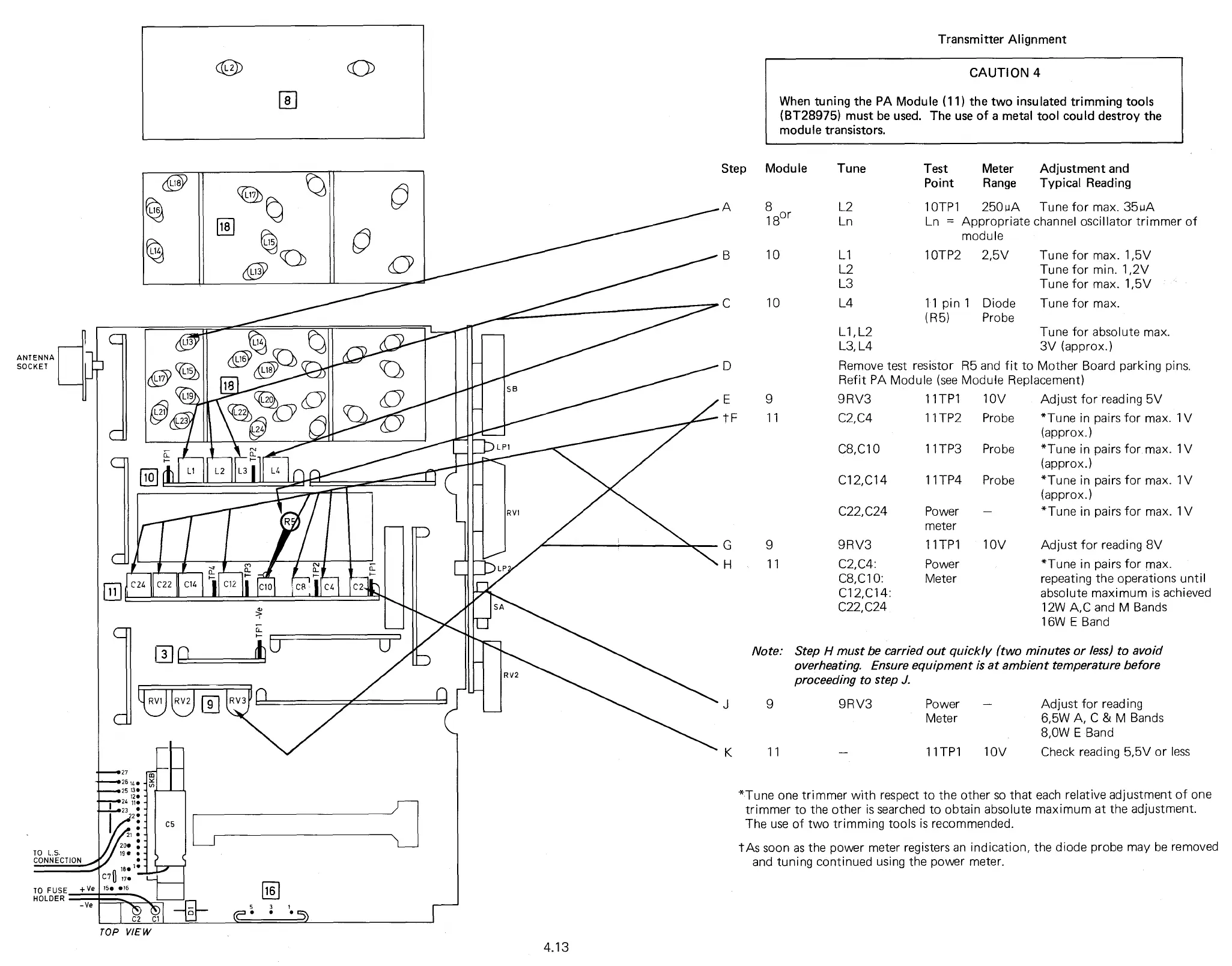
Transmitter Alignment
Step Module Tune
8
L2
18
or
Ln
10
L1
L2
L3
10
L4
Test
Meter
Adjustment and
Point
Range
Typical Reading
10TP1
250A Tune for max. 35uA
Ln = Appropriate channel oscillator trimmer of
module
10TP2
2,5V
Tune for max. 1,5V
Tune for min. 1,2V
Tune for max. 1,5V
11 pin 1 Diode
Tune for max.
(R5)
Probe
Note:
Step H
must be carried out quickly (two minutes or less) to avoid
overheating. Ensure equipment is at ambient temperature before
proceeding to step J.
10V
Probe
Probe
Probe
Adjust for reading 5V
*Tune in pairs for max. 1V
(approx.)
*Tune in pairs for max. 1V
(approx.)
*Tune in pairs for max. 1V
(approx.)
*Tune in pairs for max. 1V
Adjust for reading 8V
*Tune in pairs for max.
repeating the operations until
absolute maximum is achieved
12W A,C and M Bands
16W E Band
Tune for absolute max.
3V (approx.)
R5 and fit to Mother Board parking pins.
Module Replacement)
C22,C24
Power
meter
9
9RV3
11TP1 10V
11
C2,C4:
Power
C8,C10:
Meter
C12,C14:
C22, C24
L1,L2
L3, L4
D
Remove test resistor
Refit PA Module (see
E
9
9RV3
11TP1
tF
11
C2,C4
11TP2
C8,C10
11TP3
C12,C14
11TP4
9
9RV3
Power
Adjust for reading
Meter
6,5W A, C & M Bands
8,0W E Band
11
11TP1
10V
Check reading 5,5V or less
*Tune one trimmer with respect to the other so that each
relative adjustment of one
trimmer to the other is searched to obtain absolute maximum
at the adjustment.
The use of two trimming tools is recommended.
tAs soon as the power meter registers an indication, the
diode probe may be removed
and tuning continued using the power meter.
AD'
(94
'V
re
4
l®
,
11
-027
„..,_
426
14
--we 25 13
12
i24 11
23
2
TO L.S.
CONNECTION
200
it
180
C70
17
.
TO FUSE
HOLDER
+Ve
150 •16
-Ve
C2 Cl
TOP VIEW
ANTENNA
SOCKET
4.13
CAUTION 4
When tuning the PA Module (11) the two insulated trimming tools
(BT28975) must be used. The use of a metal tool could destroy the
module transistors.