LTE Module Series
EG25-G Hardware Design
EG25-G_Hardware_Design 59 / 100
Table 22: Pin Definition of STATUS
Indicate the module operation status
An external pull-up resistor
is required.
If unused, keep it open.
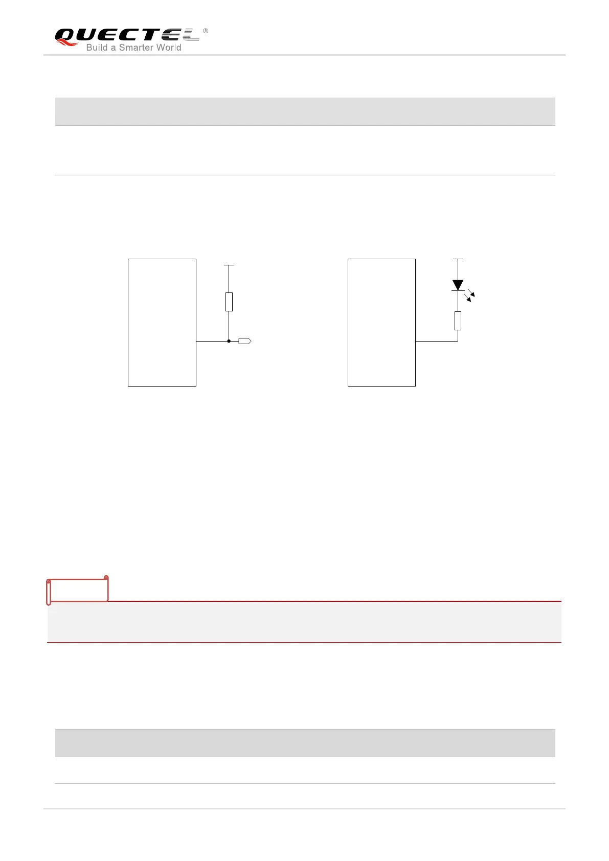
The following figure shows different circuit designs of STATUS, and customers can choose either one
according to customers’ application demands.
VDD_MCU
10K
Module
STATUS MCU_GPIO
Module
STATUS
VBAT
2.2K
Figure 30: Reference Circuits of STATUS
3.19. Behaviors of RI
AT+QCFG="risignaltype","physical" command can be used to configure RI behavior.
No matter on which port a URC is presented, the URC will trigger the behavior of RI pin.
URC can be outputted from UART port, USB AT port and USB modem port through configuration via
AT+QURCCFG command. The default port is USB AT port.
In addition, RI behavior can be configured flexibly. The default behavior of the RI is shown as below.
Table 23: Behaviors of RI