LTE Module Series
EG25-G Hardware Design
EG25-G_Hardware_Design 89 / 100
8.2. Manufacturing and Soldering
Push the squeegee to apply the solder paste on the surface of stencil, thus making the paste fill the
stencil openings and then penetrate to the PCB. The force on the squeegee should be adjusted properly
so as to produce a clean stencil surface on a single pass. To ensure the module soldering quality, the
thickness of stencil for the module is recommended to be 0.15mm~0.18mm. For more details, please
refer to document [4].
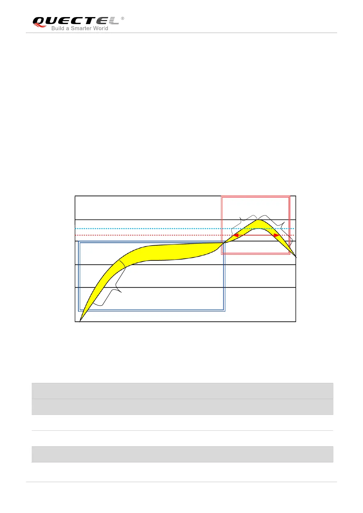
It is suggested that the peak reflow temperature is 240ºC ~245ºC, and the absolute maximum reflow
temperature is 245ºC. To avoid damage to the module caused by repeated heating, it is strongly
recommended that the module should be mounted after reflow soldering for the other side of PCB has
been completed. The recommended reflow soldering thermal profile (lead-free reflow soldering) and
related parameters are shown below.