22
Revised 4-21-10
STUDIOHUB+ BREAKOUT
+15V
+15V
-15V
+15V
-15V
-15V
SHIELD
SHIELDSHIELD
JU1
JU6JU4
JU9
JU8
JU3JU2
JU7
JU5
R5
R3
J1
R6
R4
J3
R2
R1
J2
Part # ADAPT-BO StudioHub+ Breakout Adapter
(856) 467-8000
•
Fax (856) 467-3044
•
www.studiohub.com
These internal buses and jumpers allow
+15volts, –15volts and shield to be connected
from the two studioHub+ RJ45(s) and the termi-
nal block.
A circuit path requires at least two jumpers.
JU1 install to tie terminal block shield
to internal shield bus.
JU2 install to tie terminal block –15volts
to internal –15volt bus.
JU3 install to tie terminal block +15volts
to internal +15volt bus.
JU4 install to tie StudioHub+ RJ45 J2
+15volts to internal +15volt bus.
JU5 install to tie StudioHub+ RJ45 J2
–15volts to internal –15volt bus.
JU6 install to tie StudioHub+ RJ45 J3
+15volts to internal +15volt bus.
JU7 install to tie StudioHub+ RJ45 J3
–15volts to internal –15volt bus.
JU8 install to tie StudioHub+ RJ45 J2
shield to internal shield bus.
JU9 install to tie StudioHub+ RJ45 J3
shield to internal shield bus.
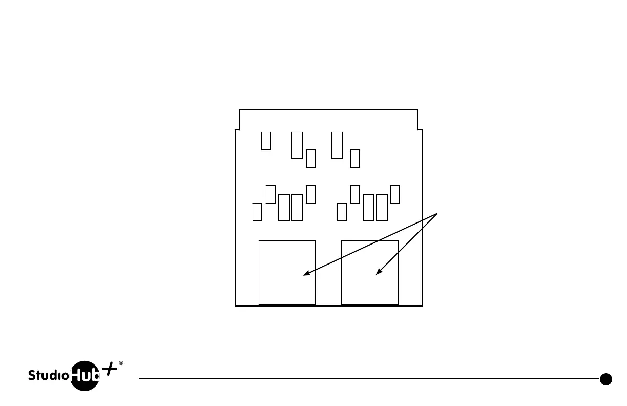
2 StudioHub+ RJ45 with
pins below in parallel
1. Left + or AES/EBU+
2. Left – or AES/EBU–
3. Right +
6. Right –
4. Power Ground
5. Future