Modified 6-18-14
18
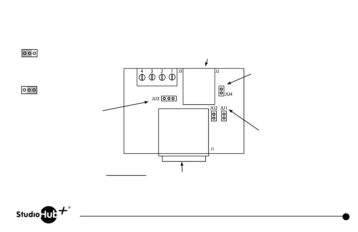
Part # SH-1XLRF
5
Pin StudioHub+ Single XLR
5
Pin Female Panel
(856) 467-8000
•
Fax (856) 467-3044
•
www.studiohub.com
JU4
Install to connect XLR pins to
XLR chassis ground
Install to connect external power
to light mic boom LED (5-15VDC)
via pins 3 & 4 on barrier
strip connector
Install to connect external power
to light mic boom LED (15VDC)
via pin 8 of RJ-45 when connected
to a standard StudioHub+ powered
Cube or Hub.
JU1, JU2
Install both jumpers to apply left
and right mic audio in parallel on
RJ-45 connector (StudioHub+
standard pins 1 & 2 for left, and
pins 3 & 6 for right). Remove both
jumpers to apply mic audio to left
channel only.
5-Pin XLR
(Mating 5-pin male in-line male
XLR connector included)
5-Pin XLR Pin Out
1 - Ground
2 - Audio +
3 - Audio –
4 - LED –
5 - +DCV
NOTE: Unused StudioHub+ RJ-45 pin 5 (CAT-5 wht/blu wire) is
connected to light mic boom LED when connected to ground
(DC voltage must be provided either via barrier strip pin 4 or
StudioHub+ pin 8. Program JU3 accordingly).
JU3
+5-15VDC
Gnd
Pull-to-Gnd to
light LED
Gnd
Made for Yellowtec Mic Arms