R&S XU 4200 Best Signal Selection
6166.5368.02.01 3.92
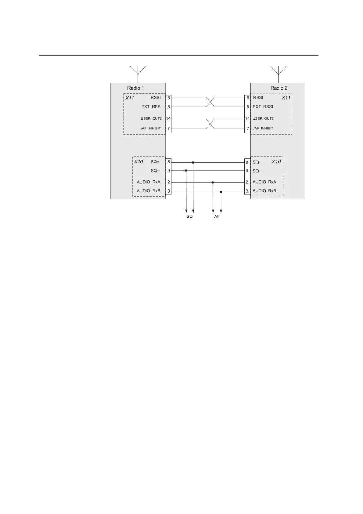
Cabling
Fig. 3.87 Cabling for best signal selection.
Note: The maximum permissible length of the cables between the two
radios depends on the cable type. Make sure that the DC loop resistance
remains < 100 Ohm for each cable.
Note: Using the E1 interface together with the BSS function is not possible.
Note: With the AUDIO_RxA and AUDIO_RxB signals connected in parallel
the output impedance will be halved to a value of 300 Ohm.
3.11.3 Configuration
Configuration of
radios using
the R&S ZS 4200
Use the Service and Maintenance Tool R&S ZS 4200 to configure the
radios for control of the best signal selection function.
1. Configure one of the two radios as the "Main (0)" and the other one as
the "Standby (1)" radio.
2. Set the “BSS Enable” parameter to "Enable" on both radios.
3. Set the “RSSI Output” parameter to "R&S Standard" on both radios.
Setting on radios
4. Set the same frequency on both radios.
Conditions
For the following parameters identical settings must be made on both
radios:
SN Squelch Threshold
RSSI Squelch Threshold
S/N RSSI Logical Operation
RX Input Sensitivity
Note: The operation of the Service and Maintenance Tool R&S ZS 4200 is
described in detail in the corres
ondin
o
eratin
manual.
 Loading...