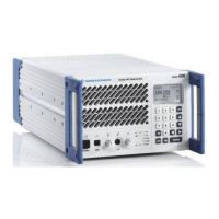
Interface Description R&S XU 4200
6.3 6166.5368.02.01
6.2.3 Common Antenna X3
Common antenna for TX and RX, N-type female
Fig. 6.3 Common antenna X3.
Entry in column D (direction): O = Output I = Input B = Bi-directional
Entry in column T (type): A = Analog D = Digital P = Power
Signal description D T Range Contact Remarks
O A TX: nominal 50 W
5 to 50 W
settable via software
AM
50 W carr/
200 W peak
X3.1
ANTENNA
I A RX:
RX/TX switch input
max. +30 dBm
GND B Ground X3.2
112 to 155.991666 MHz
TX-RX Switch X4\TX-RX Switch X4 "Radio".doc
6.2.4 TX/RX Switch X4
Output of transmit/receive switch, BNC-type female
Fig. 6.4 TX/RX switch X4.
Entry in column D (direction): O = Output I = Input B = Bi-directional
Entry in column T (type): A = Analog D = Digital P = Power
Signal description D T Range Contact Remarks
T/R_SWITCH O A TX/RX switch output
max. +30 dBm
X4.1 112 to 155.991666 MHz
GND B Ground X4.2
TX Audio Basic X5\TX Audio Bas ic X5 "Radio ".doc

 Loading...