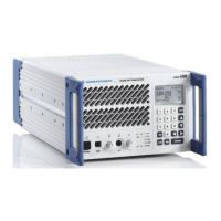
R&S XU 4200 Interface Description
6166.5368.02.01 6.14
6.2.13 RX E1 – Communication Data Connector X13
10 pins modular jack
Fig. 6.13 RX E1 − Communication data connector X13.
Entry in column D (direction): O = Output I = Input B = Bi-directional
Entry in column T (type): A = Analog D = Digital P = Power
Signal description D T Range Contact Remarks
N.C. – – – X13.1 Not connected
RX1_RING I D X13.2 Receive input negative
RX1_TIP I D
2Mbits TDM/120
Mark
– balanced: 3.0 Vp
Space
– balanced: 0 Vp
+/–0.3 V
X13.3 Receive input positive
S P – Shielding/GND X13.4 Receive ground
TX1_RING O D X13.5 Transmit output negative
TX1_TIP O D
2Mbits TDM/120
Mark
– balanced: 3.0 Vp
Space
– balanced: 0 Vp
+/– 0.3 V
X13.6 Transmit output positive
S P – Shielding/GND X13.7 Transmit ground
N.C. – – – X13.8 Not connected
N.C. – – – X13.9 Not connected
N.C. – – – X13.10 Not connected
Communication Data Connector X14\Communication Data Connector X14 "Radio".doc
1
10

 Loading...