R&S XU 4200 External Power Amplifiers
6166.5368.02.01 3.100
3.13.2.2 Cabling
Instructions
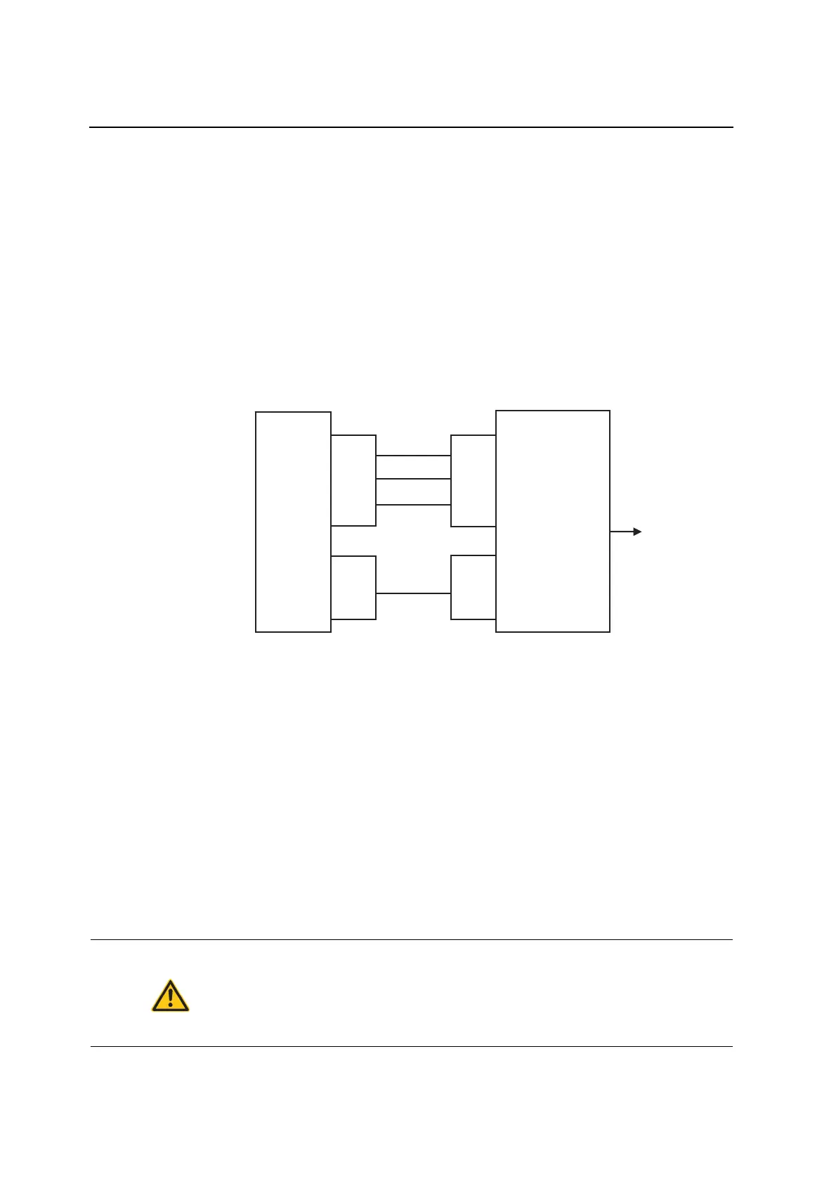
1. Connect the USER_OUT output (X7.14) of the radio to the External
Key input (Remote Facility Connector, pin 7) of the amplifier and the
USER_IN input (X7.15) of the radio to the SWR ALARM contact
(Remote Facility Connector, pin 10) of the amplifier. Connect the
second pin of the SWR ALARM contact (Remote Facility Connector,
pin 9) to ground. Connect the ground contacts of the two units (X7.3,
X7.4, X7.9 and Remote Facility Connector, pin 8 and 9) together.
2. Connect the Common Antenna output (X3) of the radio to the RF IN
input of the amplifier.
3. Connect the RF OUT output of the amplifier to the antenna.
Cabling
Fig. 3.90 Cabling for operation with the external power amplifier Jotron.
3.13.2.3 Configuration
Configuration of
radio using
the R&S ZS 4200
Use the Service and Maintenance Tool R&S ZS 4200 to configure the radio
for controlling the external power amplifier.
1. Set the “External Power Amplifier” parameter on the radio to "Jotron".
2. Set the “TX Output Power Level Low” 6 dB lower than “TX Output
Power Level Normal”. For example, when “TX Output Power Level
Normal” is set to 40 W, the “TX Output Power Level Low” shall be set to
10 W.
3. Set the “TX Output Power Level Normal” to max. of 25 W for Jotron
PAV-100 and max. of 50 W for Jotron PAV-200.
Note: The operation of the Service and Maintenance Tool R&S ZS 4200 is
described in detail in the corresponding operating manual.
ATTENTION
Risk of destruction of amplifier due to high input power
The Jotron PAV-100 VHF external power amplifier can be operated only at
a maximum input power of 25 W. The Jotron PAV-200 VHF external power
amplifier can be operated only at a maximum input power of 50 W. Higher
input power can result in destruction of the amplifier!
Note: For configuration of the amplifier please refer to the technical manual
of Jotron PAV-100/200.
15
14
3
4
9
X7
X3
USER_IN
USER_OUT
Common
Antenna
GND
REMOTE
10
7
8
9
15
Antenna
Radio
Amplifier PAV-100/200
External Key
RF INPUT
ANTENNA
SWR ALARM
GND
 Loading...