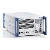
Local Control (Local Mode) R&S XU 4200
3.45 6166.5368.02.01
Radio
Type
Supported
Modes
Supported
Spacings
Accepted Offsets
to HW
Possible
Mode
Switching
Possible
Switching of
Spacing
VHF AM 25 –8 / –7.5 / –7.3 / –5 /
–4 / –2.5 / 0 / +2.5 / +4 /
+5 / +7.3 / +7.5 / +8
=> ACARS+25
=> VDL2+25
=> AM+8.33
8.33 –2.5 / 0 / +2.5 => AM+25
ACARS 25 – => AM+25
=> VDL2+25
–
VDL2 25 – => ACARS+25
=> VDL2+25
=> AM+25
–
Fig. 3.26 Possible combinations of mode/spacing/offset VHF.
Frequency (MHz)
Channel Spacing
(kHz)
Channel
112.0000 8.33 112.005
Lowest Frequency
112.0000 25 112.000
155.9917 8.33 155.990
Highest Frequency
155.9750 25 155.975
Fig. 3.27 Supported frequency ranges.
3.4.7.2.1 Explanation of Offset Activation
The ra
dio offers a numb
er of different offsets that can be activated. As the
handling of unsupported offsets is different from the handling of any other
unsupported parameter, an explanation is given here to avoid
misunderstandings. Normally unsupported parameters or commands are
rejected by the radio with an error message.
Whether an offset is supported depends on a combination of other
parameters, such as spacing or mode. Please refer to the ICD for a
detailed table with all permitted combinations of modes, offsets and
spacings that can be set to the hardware.
Note: The radio behavior is specified as follows: offsets that are not
permitted in certain spacing will be accepted and stored by the radio, but
not activated in the hardware. Only when a spacing which supports this
stored offset is activated, the offset will be activated in the hardware. The
consequence of storing the offset is that it can be read out over all
interfaces and it is displayed on the MMI, even if it is not activated in the
hardware because this combination of offset and spacing is not permitted.

 Loading...