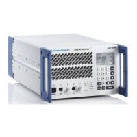
R&S XU 4200 Interface Description
6166.5368.02.01 6.4
6.2.5 TX Audio Basic X5
10 pins modular jack
Fig. 6.5 TX audio basic X5.
Entry in column D (direction): O = Output I = Input B = Bi-directional
Entry in column T (type): A = Analog D = Digital P = Power
Signal description D T Range Contact Remarks
MONITOR_TX_A O A 0 dBm ±1.5 dB
300 to 3400 Hz
600 ±15 % balanced
X5.1 RF AM demodulation
signal derived from
antenna port
@ 90 % AM mod. depth
Audio transformer
minimum 500 V isolation
to ground
AUDIO_TX_A I A X5.2
AUDIO_TX_B I A
Nominal
0 dBm ±1.5 dB
−30 to +10 dBm
settable via software
300 to 3400 Hz
600 ±15 % balanced
ALC switchable
Range ±15 dB
Total max. +15 dBm
X5.3
For 90 % AM mod. depth
Audio transformer
minimum 500 V isolation
to ground
/TEST_OC O D Low = no error
Open collector =
request for
main/standby switchover
Open collector
Ri = 10
limited to max. 6.8 V
X5.4 TEST_OC signal
generated by NOGO logic
on backplane
GND B P X5.5
V_OP_SW O P 0 V/19 to 32 V
Inactive: 0 V
Active: 19 to 32 V
Switched supply
Reverse current safe
X5.6 Operational voltage
switched
Max. 1 A for external
antenna relays. Do not
short to ground.
Note: Maximum current in
sum with X7.1/X7.2,
X10.6, and X11.1/X11.2
Corresponds to VOP LED
on front panel
1
10

 Loading...