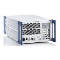
External Power Amplifiers R&S XU 4200
3.99 6166.5368.02.01
3.13.1.4 Limitations/Notes
Limitations
Please note that there are certain limitations to radio operation if an external
power amplifier is connected:
The main/standby function is not supported
The USER_OUT output cannot be used for remote control of a user via
the management system (UO (user out) GB2PP code)
The transmit signal at the antenna output of the radio is made available
with a delay of 20 ms relative to the PTT input signal.
Note: When the radio is switched off, the amplifier is still active and
consumes power.
Note: When the external power amplifier is active, only AM modulation
mode can be used.
Note: Make sure that the maximum set output power of the radio does not
exceed the maximum permissible input power of the amplifier.
3.13.2 External Power Amplifier Jotron PAV-100/200
This chapter
This chapter provides information on how to operate the radio together with
the Jotron VHF external power amplifier.
3.13.2.1 Introduction/Overview
Introduction
The radio supports the use of an external power amplifier.
The Jotron VHF external power amplifier is set to a fixed gain of 6 dB. This
means that with input power of 25 W signals will be transmitted at output
power of 100 W. With an input of maximum 50 W, the RF signal is
transmitted with 200 W.
The amplifier is operated (switched on/off) via the PTT signal which controls
the TX/RX relay of the amplifier. In standby operation the signal from the
antenna is passed through the amplifier to the amplifier's RF input. Thus,
the signal from the antenna is available at the receiver. When the PTT is
active, the signal from the transmitter is passed through the TX/RX relay of
the amplifier to the amplifier's RF input. The amplified signal is passed to
the antenna.
In case of high antenna mismatch SWR ALARM signal is generated by the
amplifier at the Remote Facility Connector, pin 9 and 10. The alarm signal
shall be connected to the radio's USER_IN input, X7.15. When the
USER_IN input is grounded, the radio switches RF Power to “Low”. CBITs
0349 “EXT PA ALARM” and 0350 “PWR REDUCED TO LOW” are
generated.

 Loading...