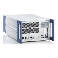
R&S XU 4200 Audio via E1 Interface (Optional)
6166.5368.02.01 3.94
3.12 Audio via E1 Interface (Optional)
0.
Audio Data via E1 Interface\Audio Data via E1 Interface "Radio".doc
This chapter
This chapter provides information about the cabling, configuration and
conditions for using the E1 interface.
3.12.1 Introduction/Overview
Introduction
The radio is equipped with an E1 interface for the digital transmission of
audio signals.
Description of
the E1 interface
The E1 interface is implemented according to ITU standards G.703, G.704,
G.711 and G.732. The frame structure is CAS multiframe. The PCM coded
audio signal (A-law) is transmitted in the timeslot TS1 and the signaling is
transmitted in timeslot TS16. The channel associated signaling (CAS) used
in TS16 is specified below.
Signaling code
The signaling is coded in bits A, B, C, D as follows (first bit = A):
CAS coding for direction to transceiver (TX)
PTT active:
PTT inactive:
1010
all other states
CAS coding for direction from transceiver (RX)
Squelch closed/Device status OK:
Level < 6 V:
Level > 6 V to 30 V:
Level > 30 V:
Device status NOGO:
Reserved:
0101
0011
0110
1100
1111
all other states
Note: Once the SQ criteria are met, the signal strength is evaluated. An
appropriate CAS code is selected and kept unchanged for the whole period
(until the SQ release).
Error handling
If NOGO errors occur in the radio, an alarm indication signal (AIS) is sent
via the E1 interface. If a CAS-coded PTT signal is received during this time,
it is ignored.
The squelch signaling is overwritten by the "Device status NOGO" signaling.
The „Alarm for Inactive Warning“ parameter can be used to enable or
disable the sending of AIS also when the radio goes to inactive mode
(stand-by). This allows implementing an automatic switchover to another
radio if the multiplexer used on site supports such function.
The PTT function will be disabled if one of the following states of the E1
interface are detected:
LOS (Loss of Signal)
LFA (Loss of Frame Alignment)
Loss of multiframe
Loss of synchronization
External D-bit set (remote alarm indication (RAI))
Other conditions that can lead to misinterpretation of CAS information
For remote control it is required to have additional LAN connection to the
remote control system (see chapter
3.5 Remote Cotrol via LAN).

 Loading...