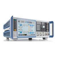
Instrument Tour
R&S
®
SMW200A
41Getting Started 1412.9220.02 ─ 21
The IEC 625 interface is in compliance with IEEE488 and SCPI. A computer for
remote control can be connected via this interface. To set up the connection, we
recommend that you use a shielded cable.
Note: To avoid electromagnetic interference (EMI) caused by open lines, always
terminate any connected IEC-bus cable with an instrument or a controller.
See also "Annex: Hardware Interfaces" and chapter "Network and Remote Con-
trol" in the user manual.
REF IN/REF OUT
Input/output for external reference signal.
The external reference is used for both paths.
INST TRIG x
Input for external trigger of sweeps and list mode.
USER x
Multipurpose connectors. The input/output signal has to be defined.
The Table 5-8 lists the signals assigned to the USER x connectors in the default
instrument state.
Table 5-8: Default configuration of the USER x connectors
USER connector Direction Default assigned signal
4 Input Global Trigger 2
5 Output Signal Valid A
6 Not used None
A dedicated LED indicates the connector status:
●
Green: an input connector
●
Yellow: an output connector
●
No light: the connector is not active
See also chapter "Local and Global Connector Settings" in the user manual.
EFC
Input connector for an EFC (external frequency control) signal for electronic tun-
ing of the internal reference frequency.
LO IN/LO OUT
Option: R&S SMW-B90
Rear Panel Tour

 Loading...