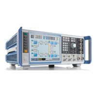
Instrument Tour
R&S
®
SMW200A
42Getting Started 1412.9220.02 ─ 21
Local oscillator input and output for phase-coherent RF signal:
●
LO IN: Input of phase coherence signal
●
LO OUT: Output of phase coherence signal
NOTICE! Risk of damaging components. Always use an appropriate 8 mm torque
wrench to tighten SMA connectors. Limit the tightening torque to 60 Ncm. Never
use an open-end wrench.
System drive (HDD/SSD)
Hard disk drive (HDD) or solid-state drive (SSD); the SSD requires option
R&S SMW-B93.
Concerning security concerns the hard disk can be removed from the instrument,
but it is bound to the specific R&S SMW. Therefore, it cannot be exchanged
between different instruments.
NOTICE! Risk of instrument damage and data loss. Removing the hard disk while
the instrument is in operation leads to data loss or even instrument damage.
Do not remove the hard disk during operation.
Display Port, DVI
Provided for future use.
LAN
The LAN interface can be used to connect the R&S SMW to a local network for
remote control, remote operation, and data transfer.
USB/USB Device
●
Four female USB type A connectors, to connect devices like a keyboard, a
mouse, a memory stick, or the R&S NRP-Z3/Z4 cable for the R&S NRP power
sensors
●
Female USB Device connector (USB type B), for example for remote control.
See also Chapter 4.2, "Connecting USB Devices", on page 24.
AC supply and power switch
The AC power supply connector and the main power switch are located in a unit
on the rear panel of the instrument.
Main power switch function:
●
Position 1: The instrument is in operation.
●
Position 0: The entire instrument is disconnected from the AC power supply.
For details, refer to Chapter 4.1.6, "Turning the Instrument On and Off",
on page 20.
Rear Panel Tour

 Loading...