Attachment and installation 3
24
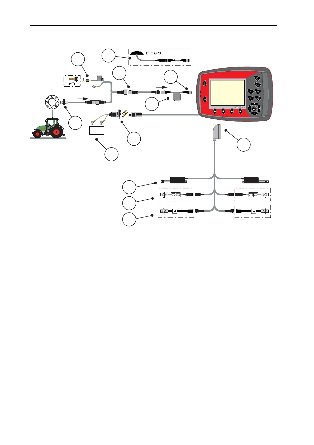
Schematic connection diagram: Power supply via ignition lock
Figure 3.5: Schematic connection diagram QUANTRON-A
(power supply via ignition lock)
[1] Serial interface RS232, 8-pin plug connector
[2] 39-pin machine plug
[3] Metering slide actuator left/right
[4] Option (level sensor left/right)
[5] Option (TELIMAT sensor top/bottom)
[6] Battery
[7] 3-pin plug connector conforming to DIN 9680 / ISO 12369
[8] Option: Y-cable (V24 RS232 interface for storage medium)
[9] 7-pin plug connector conforming to DIN 9684
[10] Forward speed sensor
[11] Option: Power supply QUANTRON-A via ignition lock
[12] Option: GPS cable and receiver
km/h
+
-
km/h
1
2
3
5
6
7
9
10
11
4
8
12

 Loading...