5
INSTALLATION
1. INSTALLATION OF RAVEN RADAR
For mounting the Radar, the following guidelines will assure proper installation:
It is suggested that a large heavy mounting bracket, (P/N 107-0159-693) be
attached to the vehicle frame for mounting the Radar.
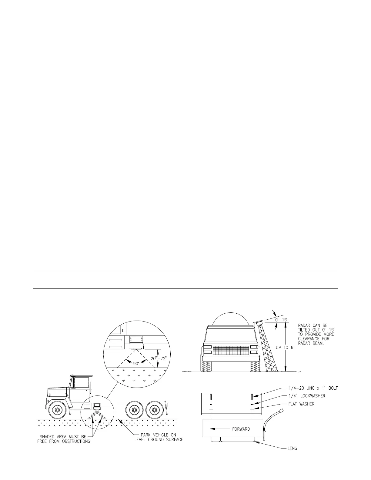
1) Park vehicle on level surface.
2) Select mounting site by considering the following:
a) The line of sight from the lens to the ground must not be obstructed by
structures or tires. Obstructions must not come closer than 20 inches to
the bottom of the Radar. See Figures 1 and 2.
b) The Radar lens must be parallel to the ground from front to back. Radar
can be tilted out 0-15 degrees to provide more clearance and miss
obstructions. See Figure 2. Figure 2.
c) The Radar should be mounted so that the length of the Radar is parallel
with direction of vehicle travel.
3) Use carpenters level to verify that mounting bracket is parallel to the ground.
4) Bolt mounting bracket to implement.
5) Bolt Radar to mounting bracket using mounting hardware. See Figure 3.
6) Connect Radar with Radar Interface Cable (P/N 115-0159-539), to the DCS 410
Console. The Red wire should be connected to 12 VDC. The White wire should be
connected to ground.
CAUTION: The connection of the Radar power in reverse polarity could result in
damage to the Radar.
FIGURE 1
FIGURE 3
FIGURE 2