6
2. MOUNTING FLOW METER AND CONTROL VALVE
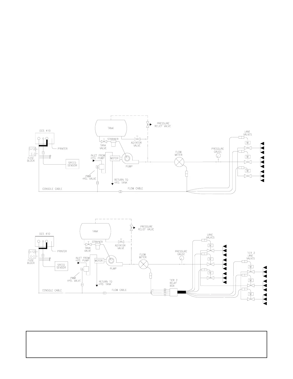
1) Mount Flow Meter in the area of the liquid control per Figure 5. All flow through
Flow Meter must go to nozzles only, i.e., no return line to tank or pump after
Flow Meter.
2) Flow must be in direction of arrow on Flow Meter.
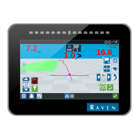
NOTE: This is two examples of application schematics.
It is essential, when using suspensions, that the system be thoroughly
rinsed out each day after use.
FIGURE 5
ANTI-ICE SCHEMATIC
TIER 2 SCHEMATIC