24
|
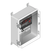
nVent.com/RAYCHEM RAYCHEM-OM-EU2032-NGCUIT3EX-EN-2203
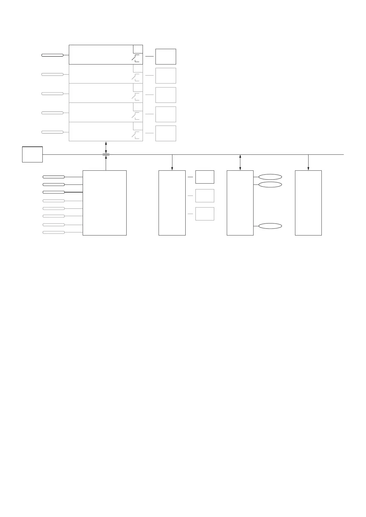
The NGC-30 software can manage up to 260 Circuits similar to that depicted above. The control Circuit concept is not limited to the
simple arrangement shown above. Multiple input circuits and “monitor only” circuits are possible as depicted on the following page.
NGC-30-CRM/-CRMS
Board
1
LC
GF
LC = Line current
GF = Ground fault
Additional
RTDs
Output
Relay 1
Local/A
RTD
2
LC
GF
Output
Relay
Local
RTD
3
LC
GF
Output
Relay
Local
RTD
4
LC
GF
Output
Relay
Local
RTD
5
LC
GF
Output
Relay
NGC-UIT
Local
RTD
B #1
C 2
D 3
4
5
6
7
8
DI 1
DI 2
RO 1
RO 2
RO ...
RTD 1
RTD 2
NGC-20
Lim RTD
RS-485
Output
Relay 1
Output
Relay
Output
Relay
DI 1
DI 2
...
DI 15
Fig. 3.6 Multiple input control circuit
NGC-
To input any device address, the modules must be connected and powered during startup of the NGC-UIT3-EX program. The program
scans for the device number(s) on the network during the update network process. The Network|Devices window lists all the device
address(es) found. The addresses listed are the only device addresses that the program recognizes as valid.
If a device is added after the NGC-UIT3-EX program has scanned the network, go to the Network window and select “Update
Network.”
Each device must have a unique device address number. For example, if the design requires both a NGC-30-CRM and a RMM2
module, and 32 is chosen for device address number for the NGC-30-CRM, then the RMM2 module cannot also use address 32. This
also applies to the other modules. (See Available Device Address Table on page 56 for device address restrictions).
 Loading...