nVent.com/RAYCHEM
|
23RAYCHEM-OM-EU2032-NGCUIT3EX-EN-2203
When a PLI module is detected in the Update Network process, the PLI tab will be added to the Network and Setup Sub-Menus.
For CRM/CRMS boards and RMM2 modules, the Resources Column indicates the RTDs that are available for use
in the Setup|RTD Screen. However, the Resources Column for PLI-SES/SPC or PLI-TT indicates the maximum number of RTDs that
could be used. Please refer to heater isometric drawings for each circuit for the assigned transmitters/RTD addresses to each circuit.
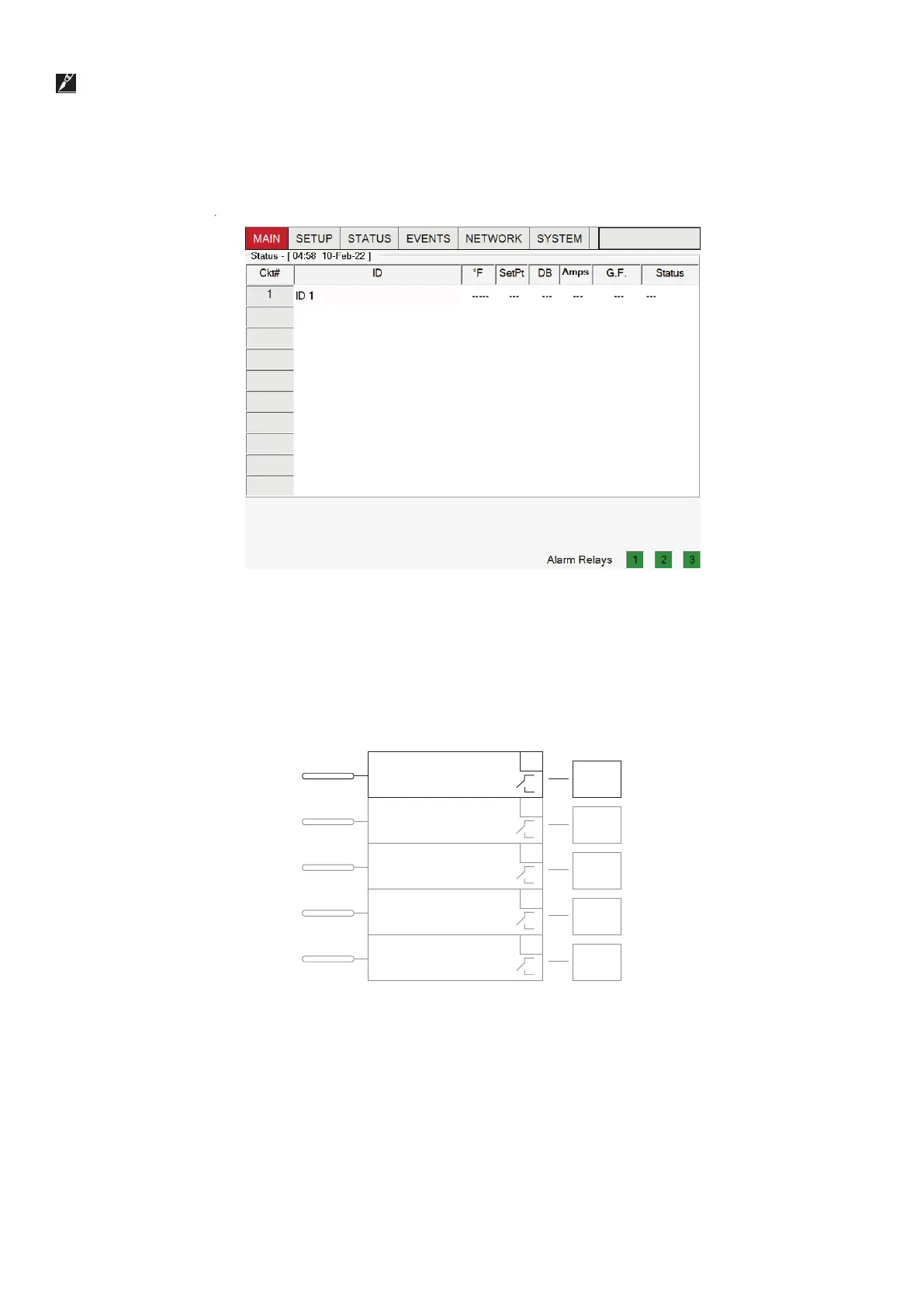
After the first system scan
Fig. 3.4 Main status window
The NGC-30 is organized around the concept of control circuits, or simply “Circuits” as they are called in the UIT3 windows. A typical
Circuit consists of one output relay device, one RTD sensor input, and one set of control parameters as shown below.
has been completed, the main window appears.
NGC-30-CRM/-CRMS Board
1
LC
GF
LC = Line current
Output
Relay 1
Local
RTD
2
LC
GF
Output
Relay
Local
RTD
3
LC
GF
Output
Relay
Local
RTD
4
LC
GF
Output
Relay
Local
RTD
5
LC
GF
Output
Relay
Local
RTD
Fig. 3.5 Simple control circuit
 Loading...