nVent.com/RAYCHEM
|
29RAYCHEM-OM-EU2032-NGCUIT3EX-EN-2203
When the sensor for control is returned to service, the controller signals the alarm has been cleared, returns the Circuit to its normal
control mode, and records both of these events.
Default is OFF
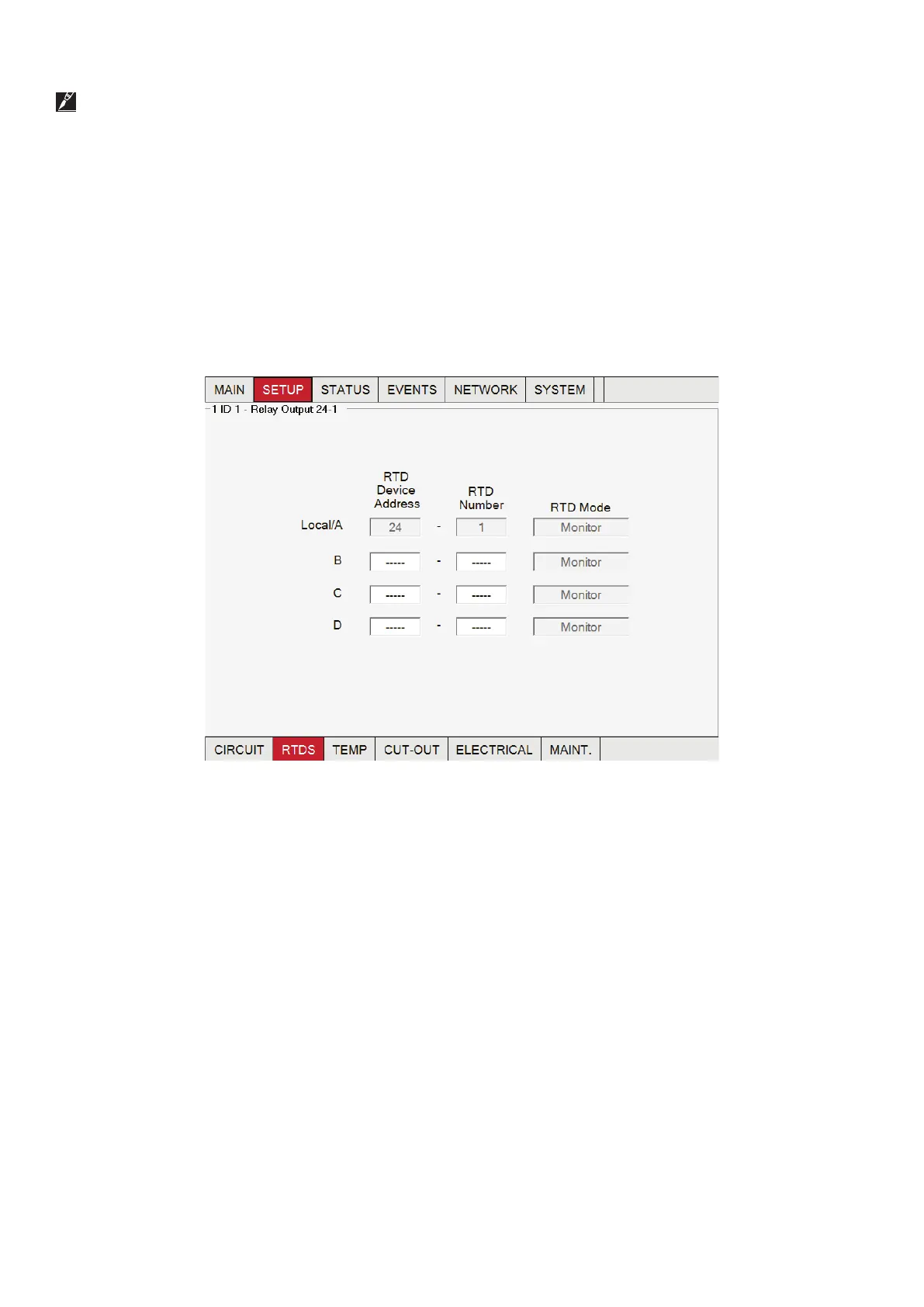
In order to assign an RTD to a Circuit, it must be shown in the Network|Devices table.
By default, each NGC-20 controller and each channel of the NGC-30-CRM/-CRMS has an associated RTD input.
The NGC-30 program first checks to see if the default RTD is available. On any NGC-30-CRM/-CRMS (5GF-C) board, the first RTD
input is automatically coupled with the first relay output; the second RTD is linked with the second output relay, etc. When a control
layout is chosen with an RMC and RMM2 then, by default, no RTD will be associated with the RMC output channel. The users decide
themselves which temperature input is linked to which output channel.
Fig. 3.11 indicates an RTD connected to the RTD 1 terminal block, so the RTD set-up screen indicates the default assignment is
already completed. This selection is grayed out because you cannot alter this default selection. In the event of a communications
failure or UIT3 failure, the circuit reverts to this default RTD for control purposes.
Fig. 3.10 Setup | RTDs window - Default RTD, hard-wired to CRM/-CRMS board
 Loading...