nVent.com/RAYCHEM
|
27RAYCHEM-OM-EU2032-NGCUIT3EX-EN-2203
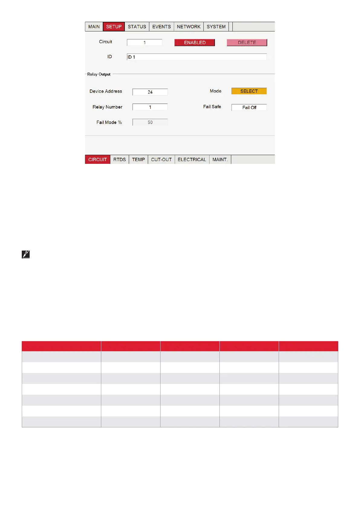
Fig. 3.9 Setup | Circuit window mode
This section defines the device/relay and the operating mode assigned to the Circuit.
The device address is the number assigned to a NGC-30-CRM/-CRMS board via the rotary selector switches. Each NGC-30-CRM/-
CRMS must be assigned a unique number (no other device can share a device address whether it’s a Relay Output device or RTD
input device). All device addresses are scanned on initial startup. If devices are added after initial startup, the user must perform a
system re-scan. (For more information on scanning for devices, see section 3.3.24 Network | Devices Window on page 56.)
Device Address Range: 0–99 (For available device addresses and specific limits, see Table 3.5 Available Device Addresses on page 54.)
If no device address is entered (0), the Circuit is limited to temperature-monitoring and temperature- alarming only.
The relay number defines which of the 5 control channels on the NGC-30-CRM/-CRMS board controls the heater’s switching device.
When the display shows dashes (---) rather than an address, no switching device has been assigned to the Circuit. For NGC-20
controllers, the relay number will always be 1.
The modes are the various control schemes that control a Circuit. There are four different control modes associated with a NGC-30-
CRM panel plus one voltage monitoring mode, and five with a NGC-30-CRMS panel plus one voltage monitoring mode.
.
NGC--CRM NGC--CRMS* RMC Elexant
On/Off X X X X
Proportional X
PASC X X X X
Always On X X X X
Always Off X X X X
Voltage X X X
Monitor Only X X
*Soft Start always active with CRMS (See Soft-Start Feature information below)
 Loading...