Wuhan Raycus Fiber Laser Technologies Co., Ltd.
User Guide of RFL-C3000XZ~RFL-C12000XZ
Figure 17 Recommend wiring diagram
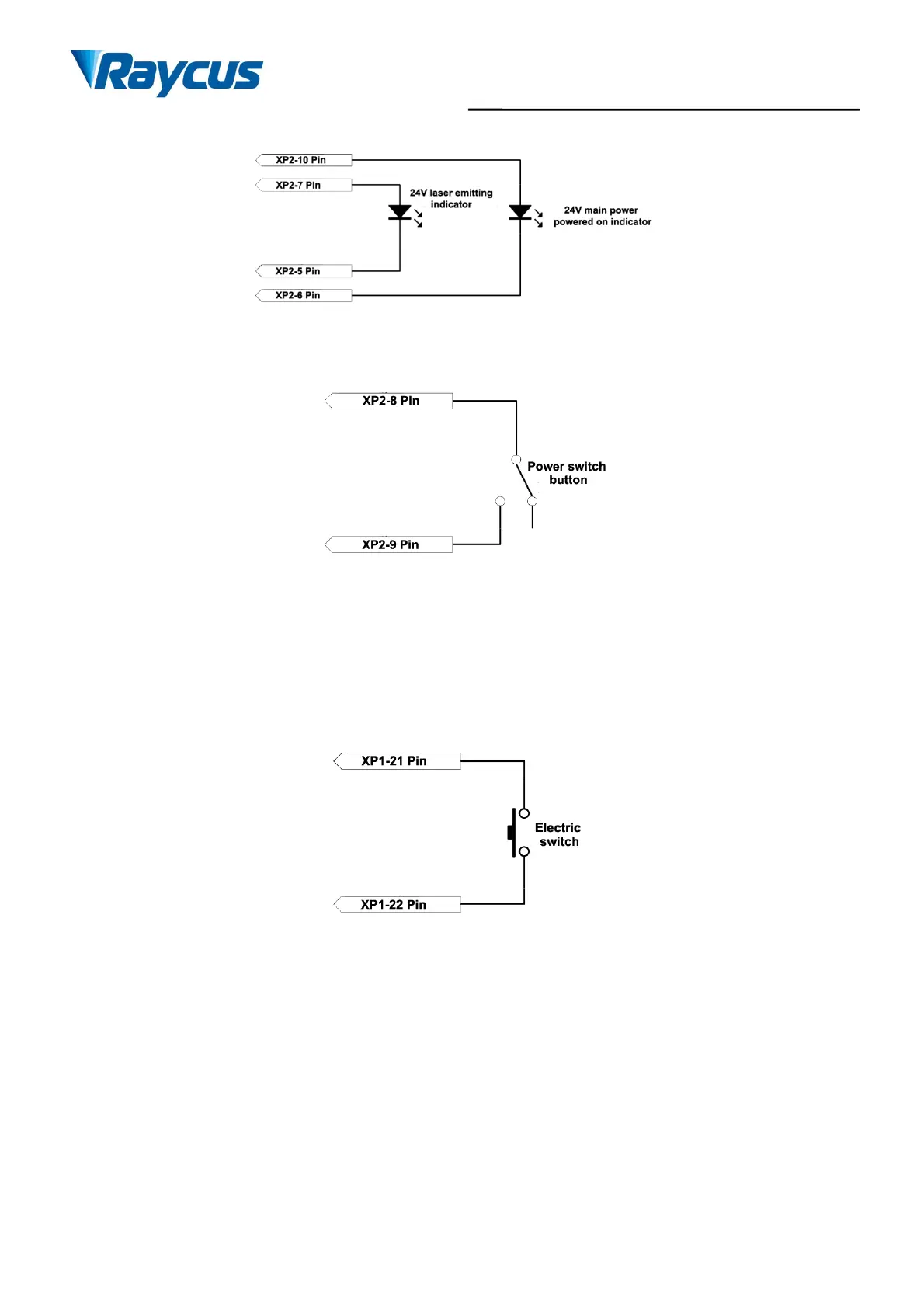
d) Power On the Remote-Control Board
Figure 18 Recommended wiringdiagram
When the laser key switch on “REM”, it must be short-connected to the 8/9 pin main control board to
power on.
e) Remote Main Power Supply
This signal is used to power on the main power supply through the XP2 interface.
Figure 19 XP2 Remote mainpowersupplywiringdiagram
f) The Control Board is Poweredon And Output
This signal is a relay output, and the relay is closed after the main control board is powered on.
4.4.2 Hardwire XP1
64 pin hard wire interface, featuring the control signal input and output for the laser working in remote
mode. The input high level is valid when it is greater than 18V, and the input low level is valid when it is
lower than 3V. Detailed interface definitions are shown in Table 6 below: