EasyManuals Logo

Reftek 130-MC User Manual

Reftek 130-MC
82 pages
To Next Page IconTo Next Page
To Previous Page IconTo Previous Page
Page #20 background imageLoading...
Page #20 background image
Rev G REF TEK 130 Multi-Channel Users Guide 5/14/2021
96223-00-UG
12 Reftek Systems Inc.
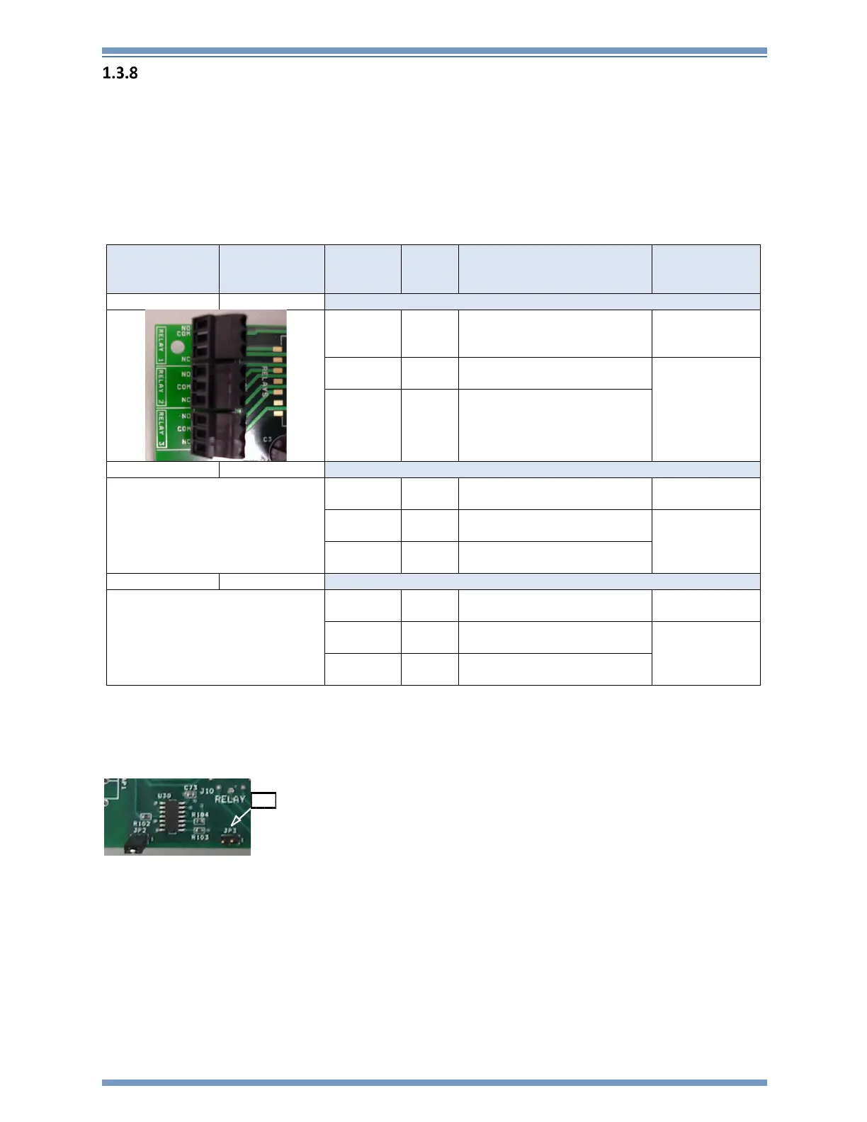
Relay RT590 Connector
The relay terminals on the 130-MC provides three relay closures for certain software set able
alarm conditions. Both Normally Open and Normally Closed contacts are provided on the relay
connector for each of the three relays. A hardware jumper is provided to change the relay
contacts from Normally De-energized (default) to Normally Energized. The relay contacts are
rated at 120 Volts AC and 30 Volts DC. The relay amp rating is equal to 1 amp. These alarm relays
can be configured using the RL command or on the Relay section of the GUI. See the SMCC Users
Guide or Command Line Reference for more information.
RT590 Terminals
Connector
MC Pin
Pin
Desc
Electrical Desc
Voltage Range
Relay 1
TB1
1
NO
Relay 1
Normally Open Contact
0-120V AC
0-30V DC
2
COM
Relay 1
Common Contact
3
NC
Relay 1
Normally Closed Contact
Relay 2
TB2
1
NO
Relay 2
Normally Open Contact
0-120V AC
0-30V DC
2
COM
Relay 2
Common Contact
3
NC
Relay 2
Normally Closed Contact
Relay 3
TB3
1
NO
Relay 3
Normally Open Contact
0-120V AC
0-30V DC
2
COM
Relay 3
Common Contact
3
NC
Relay 3
Normally Closed Contact
Note: There is an optional jumper (JP3 located near the relay connector) that can be installed on the RT580 Lid
board in order to set the three provided relays as normally energized.
JP3

Table of Contents

Questions and Answers:

Question and Answer IconNeed help?

Do you have a question about the Reftek 130-MC and is the answer not in the manual?

Reftek 130-MC Specifications

General IconGeneral
BrandReftek
Model130-MC
CategoryMeasuring Instruments
LanguageEnglish

Related product manuals