REYMSA COOLING TOWERS, INC.
www.reymsa.com
The
All-Fiberglass
Cooling Towers
5
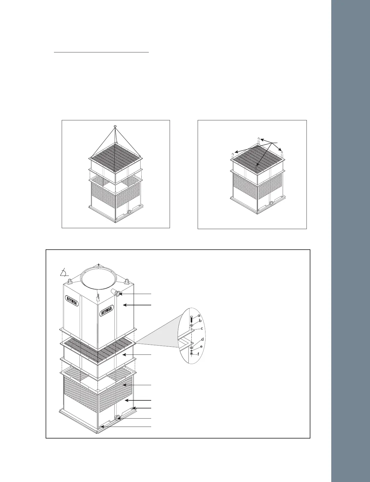
H. Only If your Tower is a RT-D model, it includes an additional part of body section (Lower Body section).
Place the Lower Body section on top of basin section, then bolt down and secure the horizontal flanges
with the stainless steel nut and bolt sets supplied by REYMSA (see Figure A-8).
I. After the Lower Body section has been set in place, remove the U-bolts located on the flange before
installing the next section (see Figure A-9).
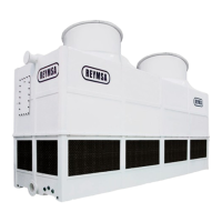
J. Assemble the body section (Upper Body section for RT-D) with the basin section (Lower Body section for
RT-D). The body section comes assembled with u-bolts for lifting; then using a crane assemble both parts,
use a drift pin to align bolt holes as the sections are being set (See figure A-7 and A-10). Make sure
that the hot water inlet, and the cold water outlet are on the same side of the Tower when assembled.
Figure A-8: Lower body installation for a Single
Fan Tower (RT-D)
Figure A-9: Removing U-bolts from Lower Body
section for a Single Fan Tower (RT-D)
Remove
1. Hot Water Inlet
2. Upper Body Section
3. 4 Anchorage Holes (one on each corner):
a. 1/2” X 2.5” Bolt
b. 1/2” Flat Washer
c. 5/8” Hole
d. 1/2” Flat Washer
e. 1/2” Lock Washer
f. 1/2” Nut
4. Lower Body Section
5. Louvers
6. Basin Section
7. Anchorage Holes
8. Cold Water Outlet
9. Steel Base Support (supplied by others).
Figure A-10: Upper and Lower Body sections installation for a Single Fan Tower (RT-D)
1
2
3
4
5
6
8
7
9
60°
RT-D
Installation