REYMSA COOLING TOWERS, INC.
www.reymsa.com
The
All-Fiberglass
Cooling Towers
35
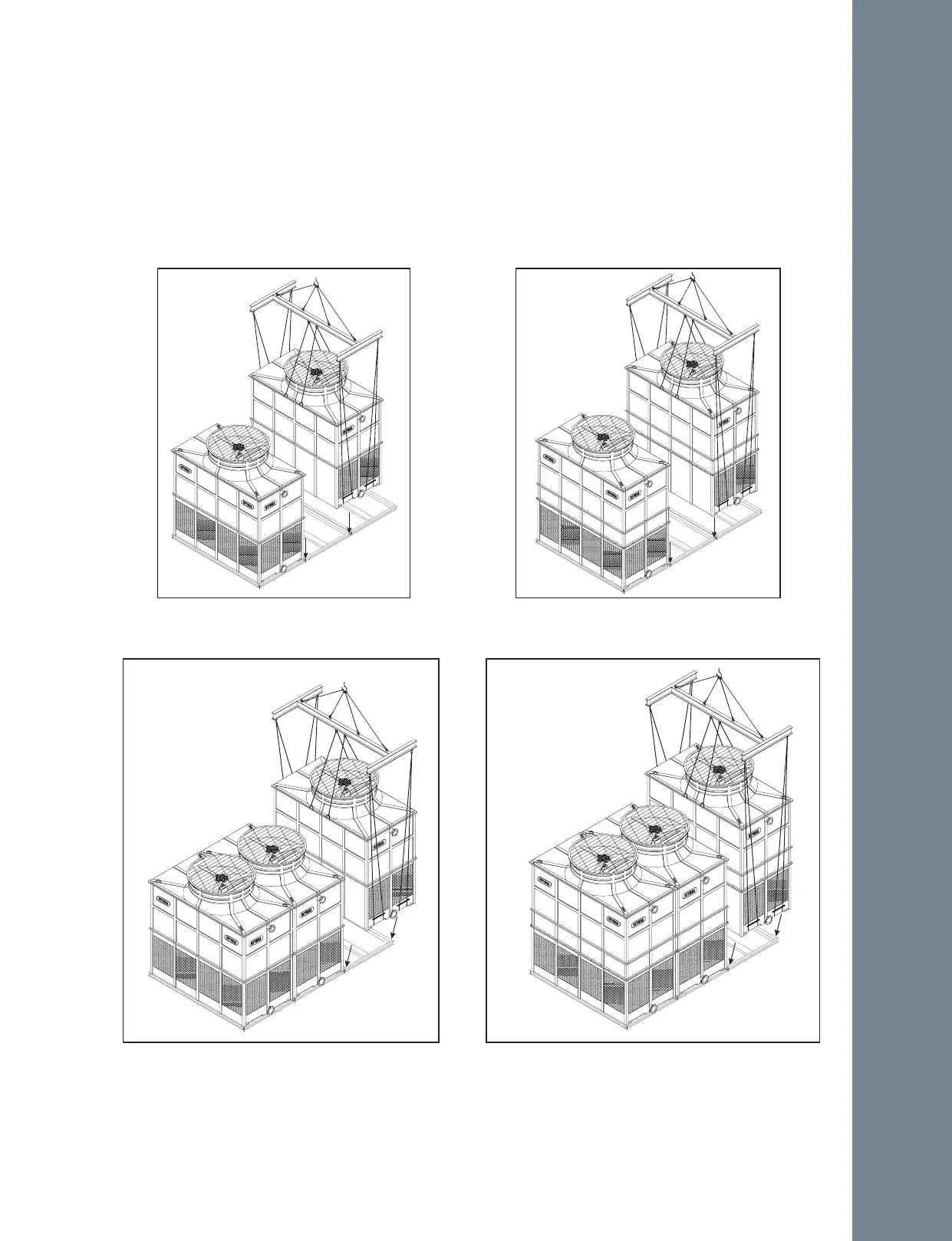
T1 Module
T2 Module
Figure A-85: T2 Module lifting and
installation (RTGM-B-L)
RTGM-B-L
T1 Module
T2 Module
Figure A-86: T2 Module lifting and
installation (RTGM-D-L & RTGM-E-L)
RTGM-D-L
RTGM-E-L
T1 Module
T2 Module
T1 Module
RTGM-B-L
Figure A-87: T1 Module lifting and installation
(RTGM-B-L)
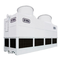
T1 Module
T2 Module
T1 Module
RTGM-D-L
RTGM-E-L
Figure A-88: T1 Module lifting and installation
(RTGM-D-L & RTGM-E-L)
C. Make sure all the modules are bolted down and secured to the steel support.
B. Repeat the previous steps to install the remaining modules. Pay attention to the correct module
arrangement; Each module is labeled alphabetically (module 1: A; module 2: B, etc.) for a proper
installation see Figure A-85 to Figure A-88).
▪ First module assembled should be T1 module, with 3 air inlet sides (2 short sides, 1 large side).
▪ Next module(s) must be T2 module, with 2 air inlet sides (short sides).
▪ The final module must be T1 type module, with 3 air inlet sides (2 short sides, 1 large side).
Installation