REYMSA COOLING TOWERS, INC.
www.reymsa.com
The
All-Fiberglass
Cooling Towers
45
A.10.3 BASIN HEATER
REYMSA offers as an optional accessory the basin heater systems designed to provide freeze protection
during shutdown or standby conditions. The basin heater system consists of an electric immersion heater(s),
a heater control panel and combination level sensor/thermostat well. Electric immersion heaters are sized
(kW rating, voltage, phase, and sensor cord immersion length) for the specific Tower, basin size, and climate.
Basin heater control panel(s) are self contained and require no control wiring. The control panel should be
mounted separately on mounts (provided by others) with close enough proximity for the thermostat sensor
capillary tube (approx. 36”) (see Figure A-109).
Installation instructions
▪ Before installation, verify that power supply voltage and phasing match the heater unit.
▪ Two inch hubs are used to insert the heater and combination level sensor / thermostat
well in the PVC couplings located at the basin (identified with labels). Immersion heater
should be located 2 inches (minimum) above the basin bottom. The access port for the
combination level sensor/thermostat well should be one inch (minimum) above the heater
but below the water level. (See Figure A-110 for recommended distances and mounting).
▪ Install the immersion heater using appropriate sealing tape or compound to prevent leakage at joint.
Sealing material must be suitable for temperature, pressure and material heated. Make sure heater is
adequately supported over its immersed length.
▪ Install stainless steel thermostat and level sensor assemble in the upper PVC adaptor.
▪ Mount control panel so thermostat and level sensor cord will reach thermostat well and level sensor
easily.
▪ The heater element connection box is water tight, unused ports must be seal to prevent leakage.
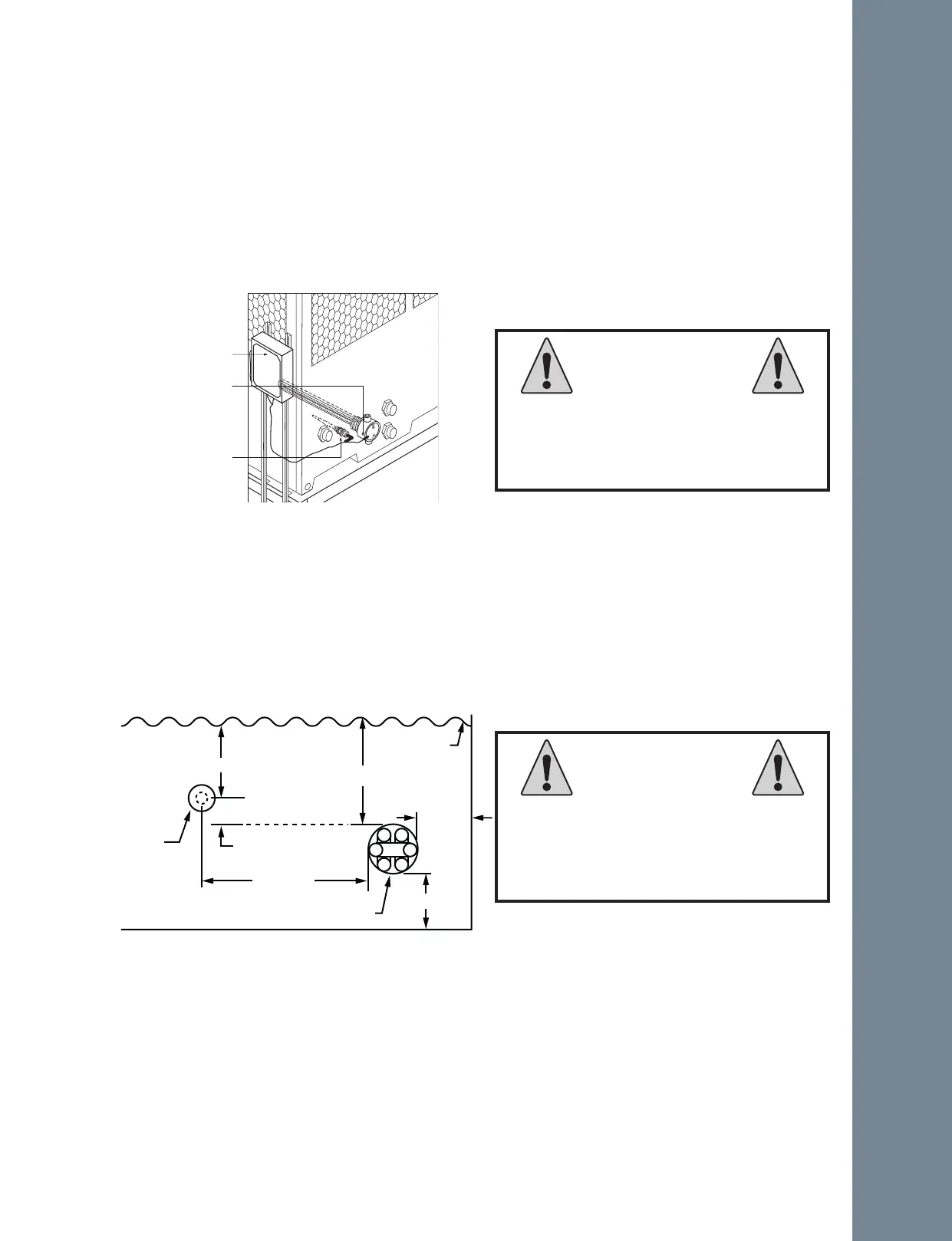
Figure A-109: Basin heater system
Control Panel
Immersion Heater
Sensor
Inmension heater should be covered
with at least 2” of fluid, while heater
is energized to prevent any failure by
overheating.
WARNING
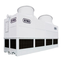
The level sensor must be installed
higher than heater while is energized
to prevent any failure by overheating.
CAUTION
Figure A-110: Recommended basin heater mounting
Installation
3” MIN TO 6“ MAX OPTIMUM)
SENSOR
6” MIN
2” MIN
2” MIN
HEATER MOUNTING
1” MIN
WATER LEVEL
2” MIN