REYMSA COOLING TOWERS, INC.
www.reymsa.com
The
All-Fiberglass
Cooling Towers
51
Installation
Configuration and Tower parts
▪ Hot water inlet
The Hot Water Inlet delivers warm water to be cooled from the process to the Cooling Tower distribution
system. A PVC pipe flange is provided for the inlet water so that a field installed butterfly valve (supplied
by others) can be installed. REYMSA recommends installing this valve in order to isolate the Tower on
multiple Tower installations and also provides a means of adjusting and/or balancing the flow through the
Cooling Tower. A ¼” NPT adaptor is provided in the piping inlet between the PVC flange and the Cooling
Tower so that a field supplied pressure gauge with a valve can be installed. This gauge is required to
determine when the proper amount of water is flowing through the Tower. The gauge should be selected
with a 0 to 15 psi range.
▪ Cold water outlet
The Cold Water Outlet serves the process with the cooled water from the Tower. REYMSA recommends
installing a valve (supplied by others) at the Cold Water Outlet to regulate flow from the Tower and also
allow Tower isolation.
▪ Make-up
Make-up water needs to compensate the water losses due to evaporation, drift and purge. To control make-
up water flow, a mechanical float valve is included by REYMSA as a standard feature. A NPT connection
is provided and marked as Make-up Water. Electric automatic fill valve with control is available as an
optional (refer to section “A.10.4 ELECTRIC WATER LEVEL CONTROL SYSTEM”).
▪ Overflow
When excess water enters the basin, it automatically flows into the Overflow and is wasted. The Overflow
connections are NPT threaded.
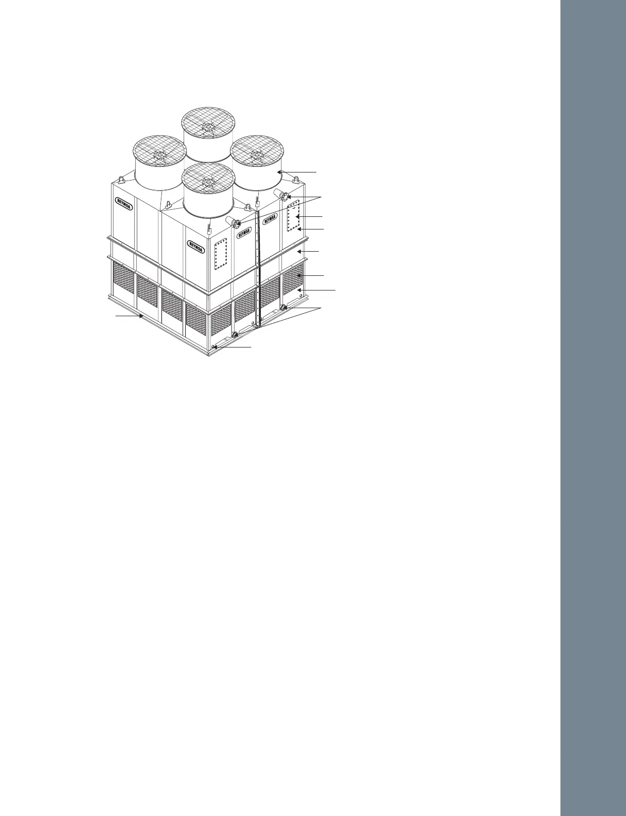
Figure A-119 Pipe connections for a Quadruple Fan Tower (RT-D)
1. Fan Section
2. Hot Water Inlet
3. Body Section (Rt-A, Rt-B, Rt-C Models)
4. Lower Body Section (Only In Rt-D Models)
5. Access Door
6. Louvers
7. Basin Section
8. Cold Water Outlet
9. Anchorage Holes
10. Steel Base Support (Supplied By Others)
11. Water Make-Up (Back Side)
12. Overflow (Back Side)
13. Temperature Sensor (Back Side)
14. Basin Heater (Back Side)
15. Drain (Back Side)
16. Purge (Back Side)
1
2
3
4
7
8
9
10
6
5
RT-D