REYMSA COOLING TOWERS, INC.
www.reymsa.com
The
All-Fiberglass
Cooling Towers
21
A.4 ASSEMBLY INSTRUCTIONS FOR RTG MODELS
Follow this procedure to assembly and install an RTG Cooling Tower. Use drift pins to align bolt holes and
use the galvanized bolts provided to torque the sections together. Replace galvanized bolt with stainless
bolts after sections are secured together.
A. Upon the arrival of the equipment to its final destination, check for any abnormality or apparent damage
on the packaging before unloading the Cooling Tower from the transportation vehicle.
B. After assuring the equipment is received in proper condition, proceed to unload it from the transportation
vehicle, piece by piece, with a crane (using a spreader bar) or forklift of the appropriate capacity, see
Figure A-46 for an example.
C. For crane lifting, it’s recommended to use a minimum lifting angle of 60º between the strap and the
horizontal. Each section of the Tower has U-bolts for lifting. Place the straps through the U-bolts (as shown
in Figure A-46) and use a spreader bar to avoid damage on the upper edge of the Tower. Don’t balance
until tensing the straps.
D. Remove the plastic wrap that surrounds the Tower and its components, and loosen the nuts and bolts that
keep the body & basin attached to the wooden pallet (those located at the bottom of basin).
E. Before Tower’s assembly, REYMSA recommends to install a steel base structure that supports the Tower’s
operational weight; also place an isolation pad (supplied by others) between the Tower and the base
structure for support purposes. Verify that the base structure has the proper dimensions (for construction,
refer to factory certified drawings). For more information, see section “A.11.1 LEVELING AND TOWER
SUPPORTS”.
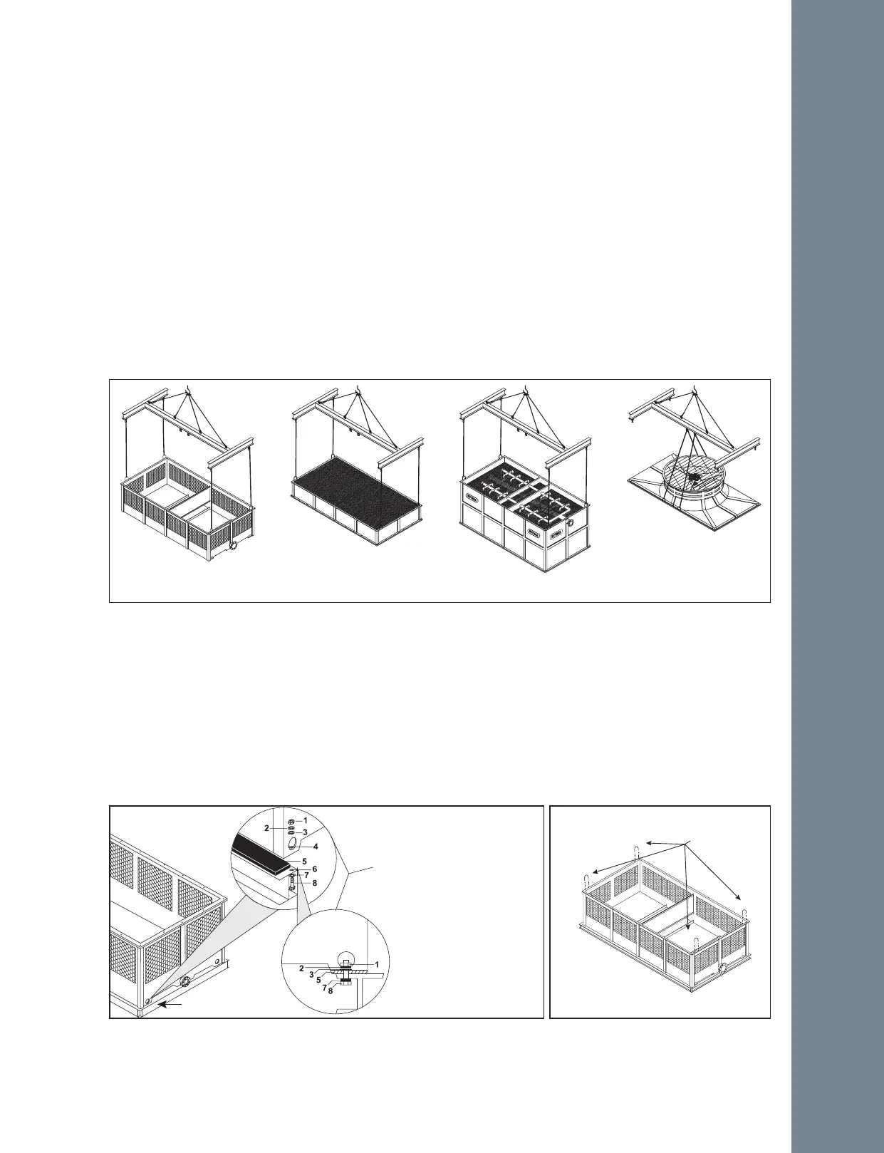
Figure A-46: Crane lifting for an RTG model.
Basin Section
Lower Body Section
(only RTG-D & RTG-E)
Upper Body / Body Section
Fan Deck
Steel base structure
(Supplied by others)
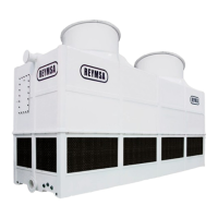
Figure A-47: Typical anchorage for an RTG model.
4 ANCHORAGE HOLES
(ONE ON EACH CORNER)
1. 3/4” Nut
2. 3/4” Lock Washer
3. 3/4” Flat Washer
4. 3/4” Anchorage Holes
5. Isolation Pad
6. ≈1” Hole
7. 3/4” Flat Washer
8. 3/4” X 3” Bolt
(Supplied by others)
Figure A-48: Removing U-bolts from
basin section of an RTG model.
Remove
Installation