REYMSA COOLING TOWERS, INC.
www.reymsa.com
46
BRANCH CIRCUIT
PROTECTION
SUPPLIED BY OTHERS:
TRANSFORMER
24V SECONDARY
YELLOW
RED
YELLOW
INDEECO CONTROLS
SERIES TL
COMBINATION
TEMPERATURE
LIQUID LEVEL CONTROLLER
SENSOR PROBE /
CORD ASSY
SHIELDED CABLE
G2
G1
T2
T1
SH
C
NO
CT
N
120
240/24
C1
C2
C1
C2
G
NC
(OPTIONAL)
HI-LIMIT PUMP
INTERFACE, ETC.
SUPPLIED
BY OTHERS
OPTIONAL THERMAL
CUTOFF (TYP)
HEATHER #2
(IF REQUIRED)
HEATHER #1
INSTALL JUMPER IF
NO REMOTE SAFETY
INTERLOCKS
DELTA OR WYE CONNECTED
MAIN
DISCONNECT
SWITCH
L1
G
L2
L3
FUSING
OPTION “CB”
CIRCUIT BREAKER
L1
L2
L3
L1
L2
L3
L1
L2
L3
T1
T2
T3
L1
L2
L3
CONTROLLING
CONTACTOR
COOLING TOWER CONTROL PANEL
3 PHASE 1 CIRCUIT (NO DISC SWITCH)
OPTION “F”
SUPPLEMENTARY
FUSING
THREE PHASE
LINE VOLTAGE
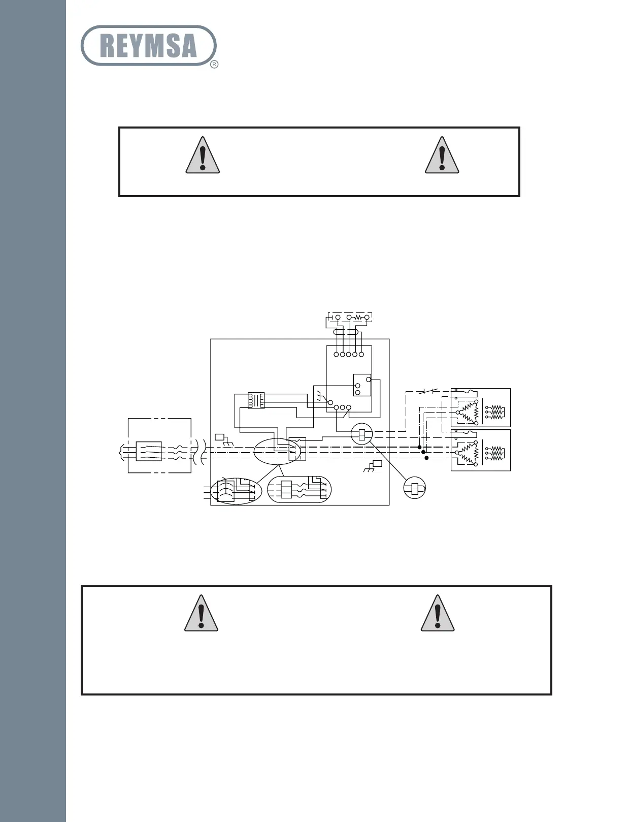
▪ Insert thermostat bulb and secure it with supplied metallic retainer.
▪ Plug level sensor cord onto the stainless steel sensor. Use silicone spray to disburse moisture and ease
installation if required.
▪ Using suitable wire connect heater to panel on “T” terminals, located on right side of contactor in panel
(See Figure A-111).
▪ Using suitable wire from an overload protected disconnect device, connect to the “L” (line) terminals of
the panel contactor, located on the left side of contactor in panel (see Figure A-111).
▪ Set thermostat in panel to meet your requirements.
Do not allow moisture to enter cap before installing on sensor.
WARNING
Improper operation, maintenance or repair of basin heater can be dangerous and could
result in injury or equipment damage.
Safety precautions and warnings are provided in section “D.6 BASIN HEATER “
of this manual.
WARNING
Figure A-111: Basin heater control panel diagram
Installation