REYMSA COOLING TOWERS, INC.
www.reymsa.com
12
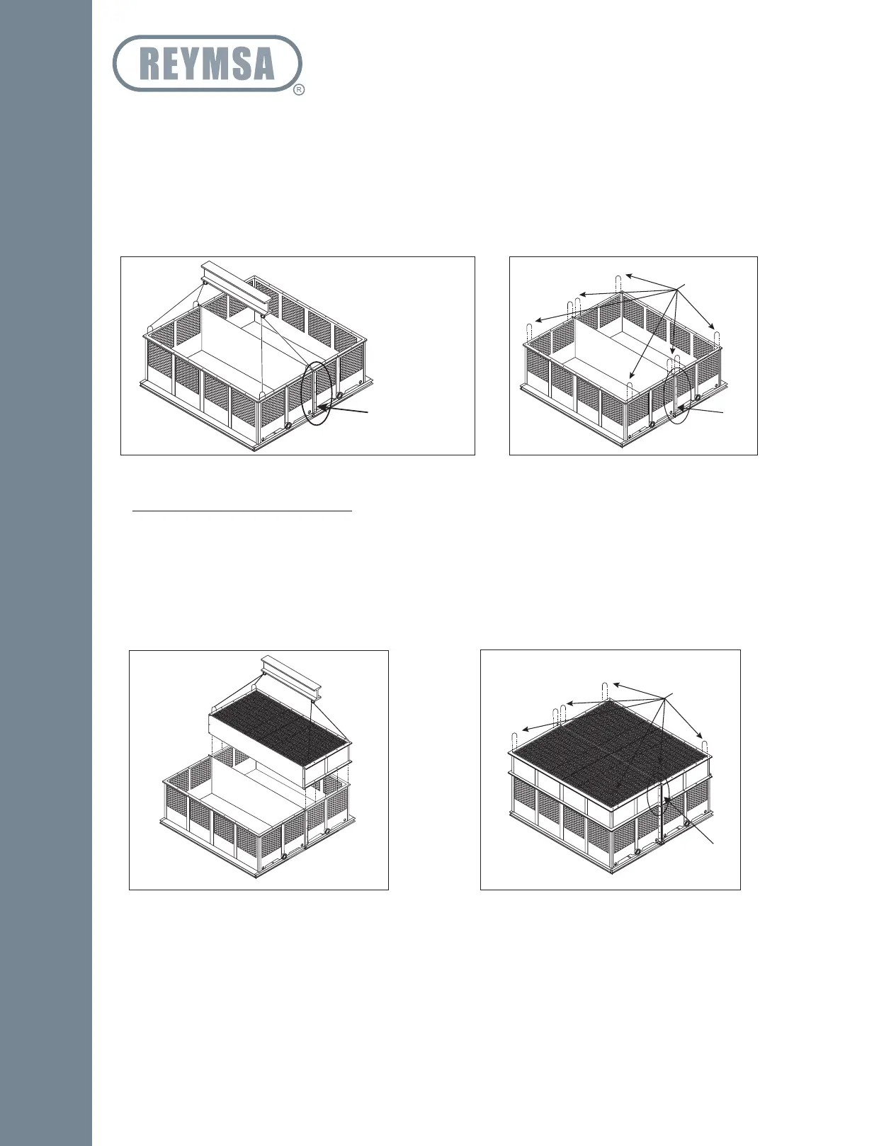
G. Place the basin section #2 of the Tower following the same instructions of step F. Is strongly recommended
the use of the spreader bar as illustrated on Figure A-26. Once the both section are in the structural
base, then proceeds to bolt together the vertical flanges of basin sections 1 & 2; use firsts the galvanized
bolts and nuts to join sections (supplied by REYMSA); then replace the galvanized bolts with the stainless
steel nut and bolt set supplied by REYMSA and secure both sections to the structural base.
H. After the basin has been set in place, remove the U-bolts on top of each corner before installing the body
section (see Figure A-27).
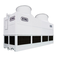
I. Only if your Tower is RT-D model: This includes additional part of body section (Lower Body section).
Place Lower Body section #1 on top of basin section #1, then bolt down and secure the horizontal
flanges with the stainless steel nut and bolt sets supplied by REYMSA. See Figure A-28.
J. Follow the same instruction to install the Lower Body section #2 on top of basin section #2. Once both
sections are installed, then proceed to bolt together the vertical flanges of Lower Body section 1 & 2;
use first the galvanized bolts and nuts to join sections, once both section are well together, then replace
galvanized bolts with the stainless steel nut and bolt sets supplied by REYMSA. Remove U-bolts from both
sections (see Figure A-29).
Vertical
Flanges
Figure A-26: Basin section 2 installation for a Quadruple Fan Tower
BASIN SECTION
Figure A-27: Removing U-bolts from basin
for a Quadruple Fan Tower
Remove
Vertical
Flanges
Figure A-28: Lower body section 1 installation for
a Quadruple Fan Tower (RT-D)
Figure A-29: Removing U-bolts from Lower Body
section for a Quadruple Fan Tower (RT-D)
Remove
Vertical
Flanges
Installation