EasyManuals Logo

RGBlink CP 3072 User Manual

RGBlink CP 3072
75 pages
To Next Page IconTo Next Page
To Previous Page IconTo Previous Page
Page #23 background imageLoading...
Page #23 background image
2. Hardware Orientation
CP 3072 Back Panel
CP 3072 User Manual 23
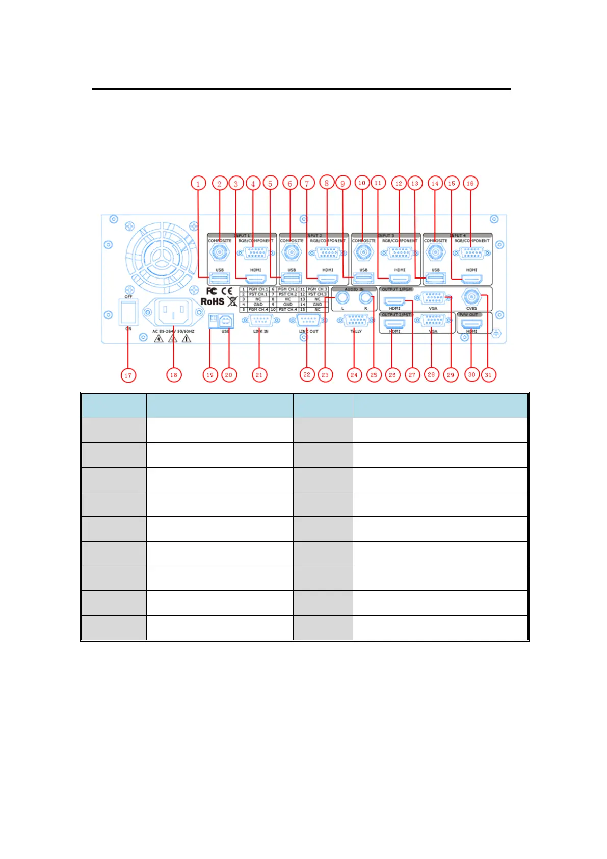
CP 3072 Back Panel
The figure below illustrates the professional interface and control signals of
CP 3072 back panel.
NO
INTERFACE
INTERFACE
1. 5. 9. 13
USB input USB-B port
Audio input port
2. 6. 10. 14
CVBS input BNC port
TALLY light
3. 7. 11. 15
HDMI/3G-SDI input
HDMI program output HDMI-A port
4. 8. 12. 16
VGA input DB15 port
VGA program output DB15 port
17
Switch
CVBS program output BNC port
18
Power IEC-3
HDMI preview output HDMI-A port
19
Dial Switch
VGA preview output DB15 port
20
USB Interface
HDMI PVW output HDMI-A port
21. 22
RS-232 Interface
CONT Interface
19: Dial Switch
If the two dial switches are downwards, the device is in normal work, and if
they are upwards, the device is in upgrade state. OLED module light is

Table of Contents

Questions and Answers:

Question and Answer IconNeed help?

Do you have a question about the RGBlink CP 3072 and is the answer not in the manual?

RGBlink CP 3072 Specifications

General IconGeneral
BrandRGBlink
ModelCP 3072
CategoryControl Panel
LanguageEnglish