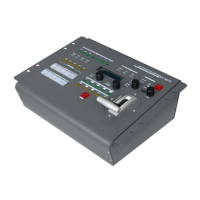
2. Hardware Orientation
CP 3072 Back Panel
CP 3072 User Manual 24
off when the device is in upgrade state. Some of the button lights turn on,
and the device will not work.
20: USB Interface
Used for firmware upgrade.
21. 22: RS-232 Interface
Used for cascade and firmware upgrade.
21: LINK IN is serial male port.
22: LINK OUT is serial female port.
LINK IN is the serial communication interface of RS-232 control protocol
and multiple cascading control.
LINK OUT is the serial communication interface of multiple devices
cascading control, connect devices through DB9 serial cable.
Note
CP 3072 V1.1 cannot support this function.
INPUT Interface
It includes 4 CVBS inputs by BNC port, 4 USB inputs, 4 HDMI inputs (only
for CP 3072), 4 3G-SDI inputs (only for CP 3072S), 4 VGA inputs by DB15
port, and 1 group of Audio L and Audio R input.
23. 25: Audio Input
Audio input, connect the audio signals of the DVD player, hardware player
and digital box.
1. 5. 9. 13:USB Input
USB input, can access the USB device or mobile hard disk with USB
storage function. Support general image and video formats.
Note
CP 3072 V1.1 can only support video formats.

 Loading...