Electrical Components
SM 4-47 M018/M019
Replacement
&
Adjustment
4.11.4 INTERLOCK SWITCHES
1. Operation panel ( p.4-4)
2. Rear cover ( p.4-3)
3. Left cover ( p.4-5)
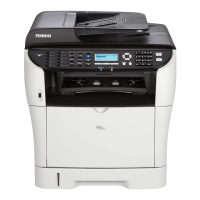
4. Remove the spring [A].
5. Interlock switch base [B] (
x 4, all s)
Remove all the connectors after the interlock switch base has been removed.
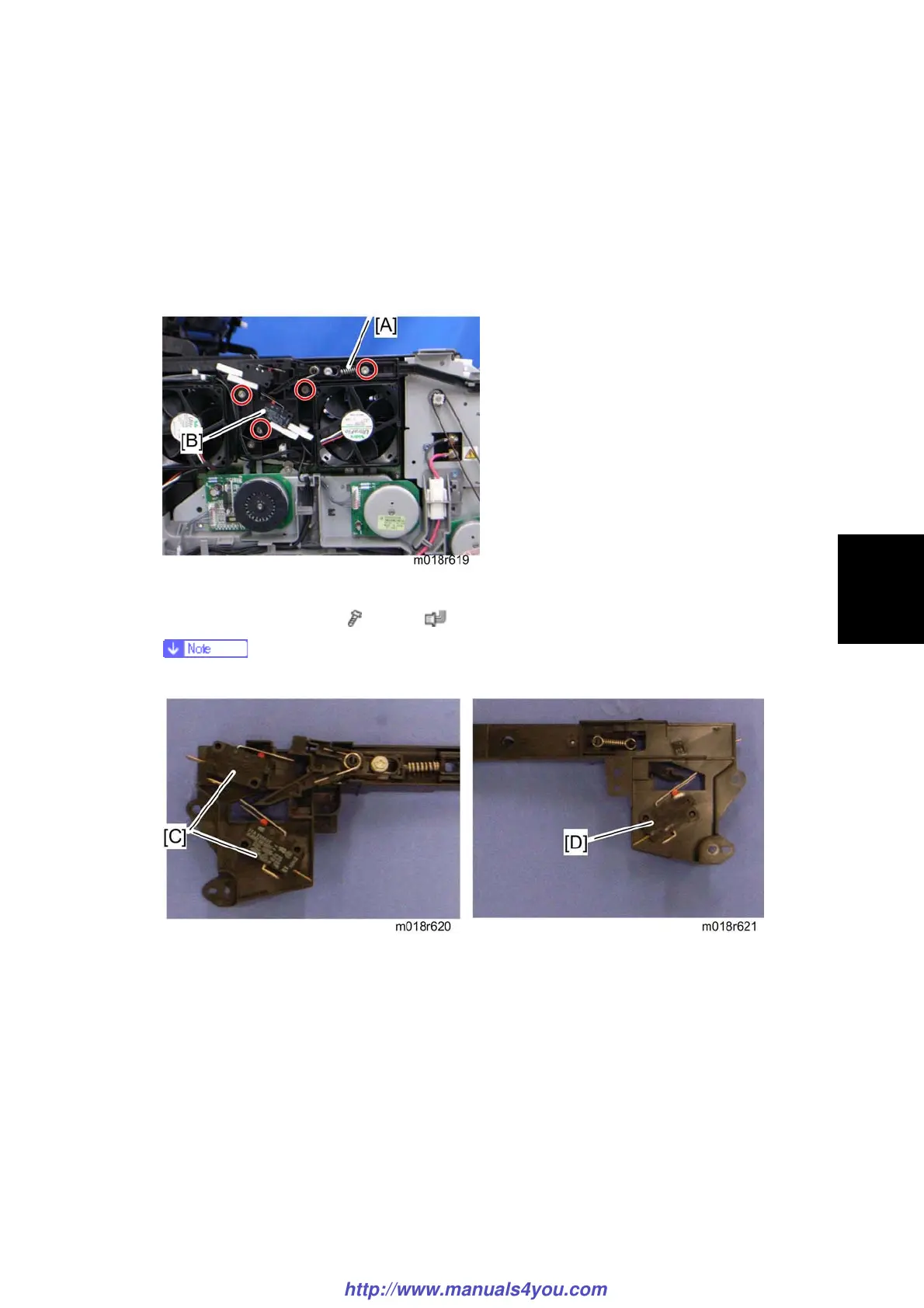
6. Two interlock switches [C] at the outside of the base and one interlock switch [D] at the
inside of the base (hooks)
http://www.manuals4you.com

 Loading...