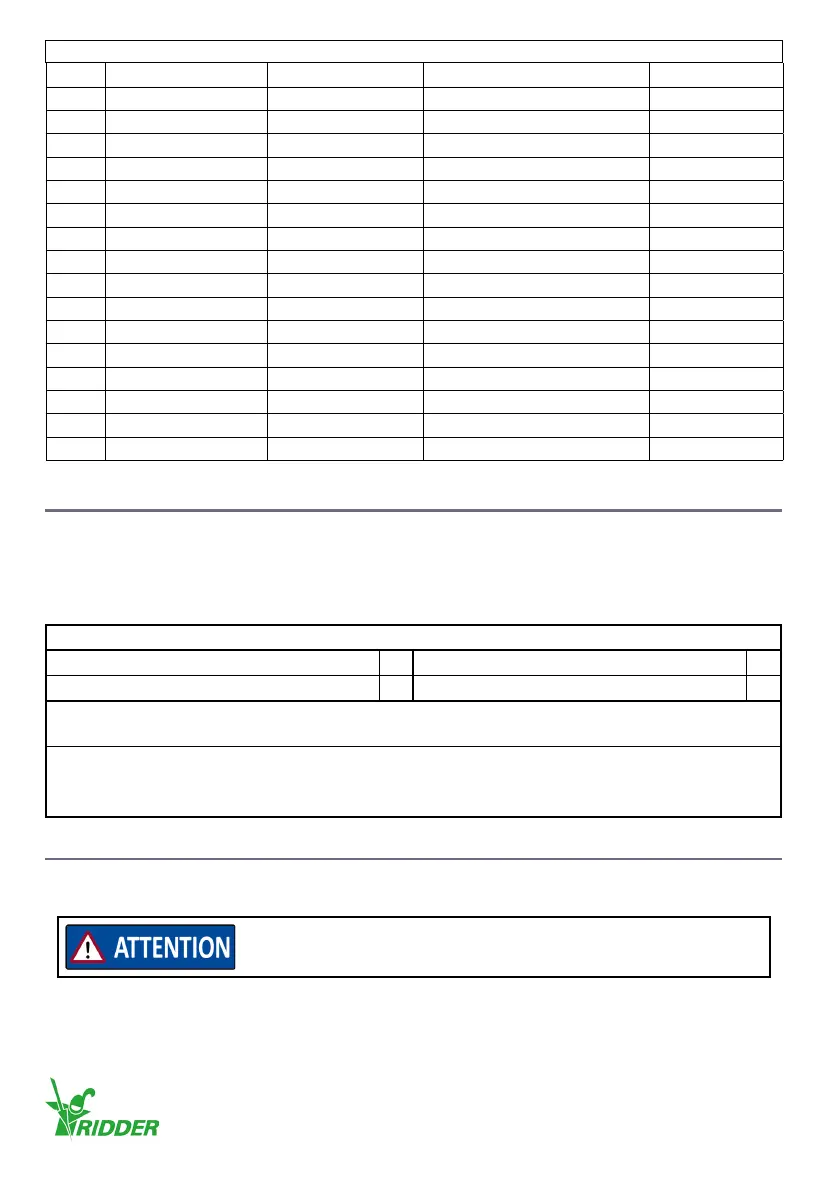
Electrical
X8 MC Type Supply voltage Current
1 +24V Power supply 24 V DC Max 15.7 mA
2 Direcon A Input 24 V DC 2.1 mA
3 Auto Input 24 V DC 2.1 mA
4 Direcon B Input 24 V DC 2.1 mA
5 LED Output 24 V DC 4.7 mA
6 LED Output 24 V DC 4.7 mA
X9 Limit switch IN Type
Supply voltage Current
1 Common Power supply 7 V DC 3.3 mA
2 Direcon B Input 7 V DC 1.1 mA
3 Direcon A Input 7 V DC 1.1 mA
4 Safety Input 7 V DC 1.1 mA
D1-D4 LED
D1 Green
D2 Red
D3 Red (RPU)
D4 Red (RPU)
4. INSTALL INSTRUCTIONS
Installaon is only permied to approved personnel. The RLL400 control-unit is available, as part of
a drive unit, on a RW motor gearbox.
Do a check of the supplied parts in the table that follows.
Parts list *
580000-RLL400 control unit 1x 500000P-RW motor gearbox (RLL type)** 1x
* Minimum parts list: Drive unit without oponal parts and accessories.
** Motor gearboxes have spring washers and bolts M10x20 (2x), M10x25 (3x/4x) or M12x25 (4x).
NOTE: Bolts M12 (4x), spring washers and nuts are accessories for RW1000 thru RW2000 motor gearboxes.
4.1 Special tools and equipment
No special tools or equipment are necessary to install, to connect or for commissioning.
Make sure that the correct equipment and tools are used.
Ridder Drive Systems B.V.
T +31 (0)341 416 854 - F +31 (0)341 416 611 - I ridder.com
12