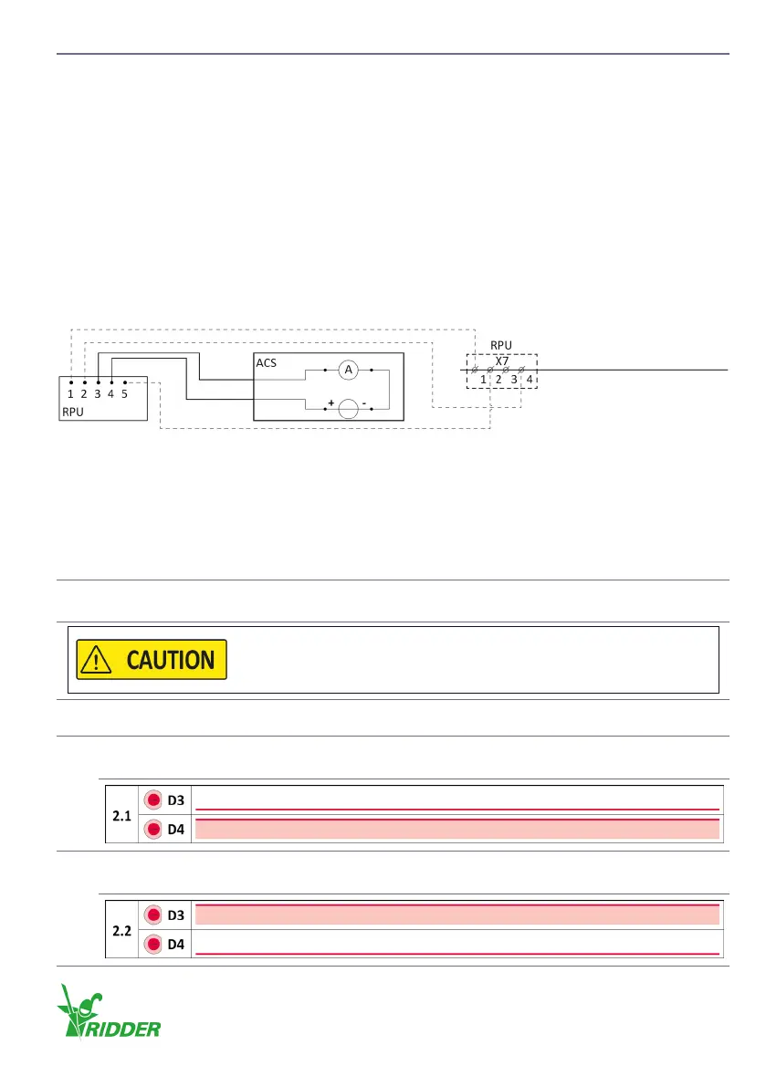
5.10 OPTIONAL - Posion Feedback (RPU)
You can connect a digital posioning-meter (RPU) and an automac control system (ACS) to the
RLL400 control-unit.
Ridder Drive Systems connected the wires that follow:
• The power supply (connecon 1 and 2) to connector X7 (connecon 1 and 4).
• The reference input (connecon 5) to connector X7 (connecon 2).
Complete the RPU connecons. Obey the diagram ① and the check procedure ②. Also refer to
the manual of the ACS.
① Connecng - Feedback (4-20 mA)
• Make sure that the power supply is 24 V DC from an external source.
• Connect the posion feedback (connecon 3 and 4) to the ACS.
② Check - Reference-input RPU
• Do the reference-input check (connecon 5) that follows when you want to use reference
monitoring and to set the reference again. Obey the check procedure to connect the RPU
connector X7 correctly.
u
Descripon
1
Select which duty switch (ES11 or ES12) you want to use as switch for the RPU reference-
monitoring. Let the motor turn in the direcon of this duty switch unl it disconnects.
To prevent damage or injury, do not go across the limit posions of
the operated system!
2
LED D3 or D4 will come on on control board (A2). Obey the instrucons in 3-A or 3-B.
3-A
Blink code is 2.1. The LED D4 (RPU CAL. A) comes on. Refer to §6.2 and §9.2.
Go to step 4-A.
3-B
Blink code is 2.2. The LED D3 (RPU CAL. B) comes on. Refer to §6.2 and §9.2.
Go to step 4-B.
Control board A2
24 V DC4-20 mA
Ridder Drive Systems B.V.
T +31 (0)341 416 854 - F +31 (0)341 416 611 - I ridder.com
19