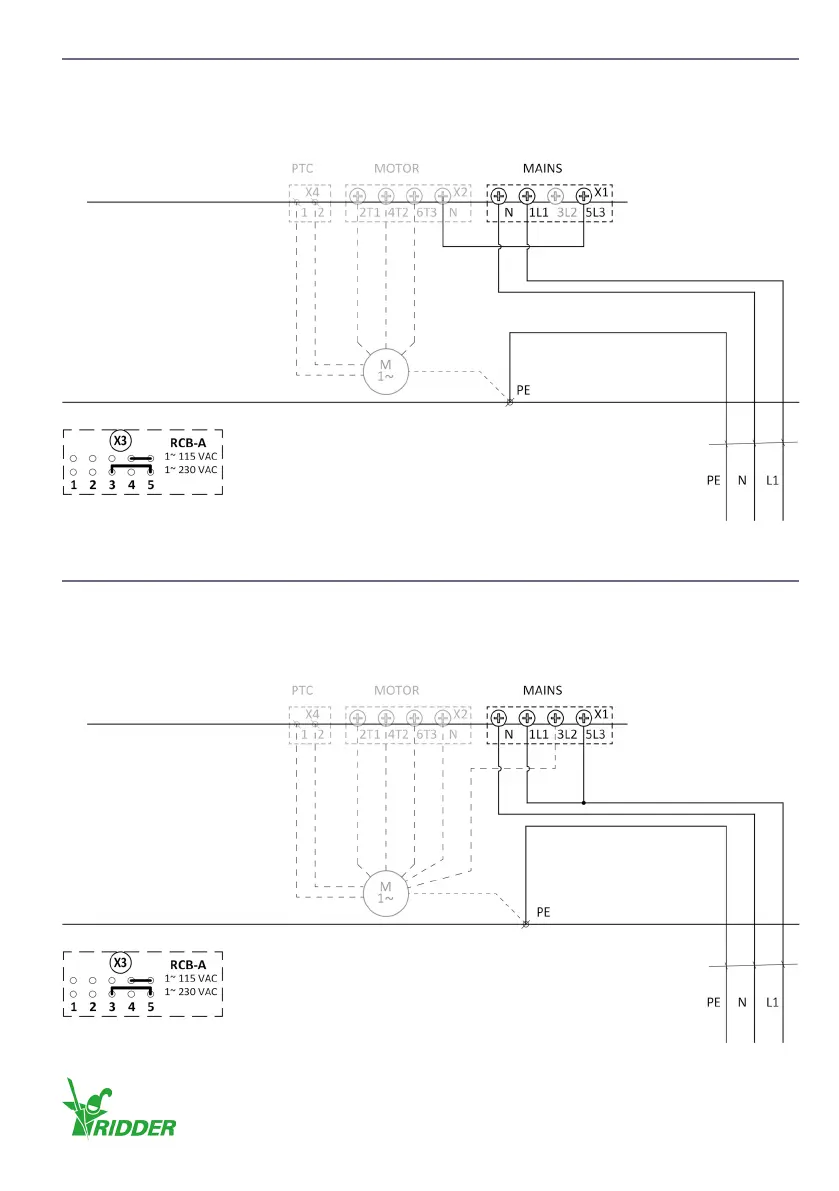
5.6 1-phase 3-wire electric motor (115-230 VAC)
• Make sure that the conguraon (RCB-A) on X3 (TRANSFORMER) agrees with the supply voltage!
• Ridder Drive Systems connects X2 (MOTOR) and X4 (PTC).
• Connect the supply voltage to X1 (MAINS) and PE (protecve earth).
5.7 1-phase 5-wire electric motor (115-230 VAC)
• Make sure that the conguraon (RCB-A) on X3 (TRANSFORMER) agrees with the supply voltage!
• Ridder Drive Systems connects X2 (MOTOR) and X4 (PTC).
• Connect the supply voltage to X1 (MAINS) and PE (protecve earth).
Control board A2
A1
(in) (out) (in)
3 x 1.5 mm²
Control board A2
A1
(in) (out) (in)
3 x 1.5 mm²
Ridder Drive Systems B.V.
T +31 (0)341 416 854 - F +31 (0)341 416 611 - I ridder.com
17
 Loading...