4.2 Installaon
The condions and starng points that follow are applicable for installaon. Make sure that the
working condions comply with the, local or naonal, laws and regulaons.
• Do not remove the product from the packaging unl a short me before the installaon.
• Use the correct work equipment and accessories (belts, chains, pallets or such) if it is not
permied or possible to put the product manually in posion.
• Ridder installed the RLL400 control-unit on a RW motor gearbox.
• Only use a permied mounng posion when you install the RW motor gearbox with control-
unit. Refer to the product manual of the used RW motor-gearbox at ridder.com.
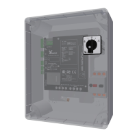
• The RLL400 gives informaon about the system with LEDs on the control board. Thus, easy access
and a sasfactory view is recommended for the locaon of the RLL400.
5. CONNECT INSTRUCTIONS
Only to approved personnel it is permied to do the connect instrucons.
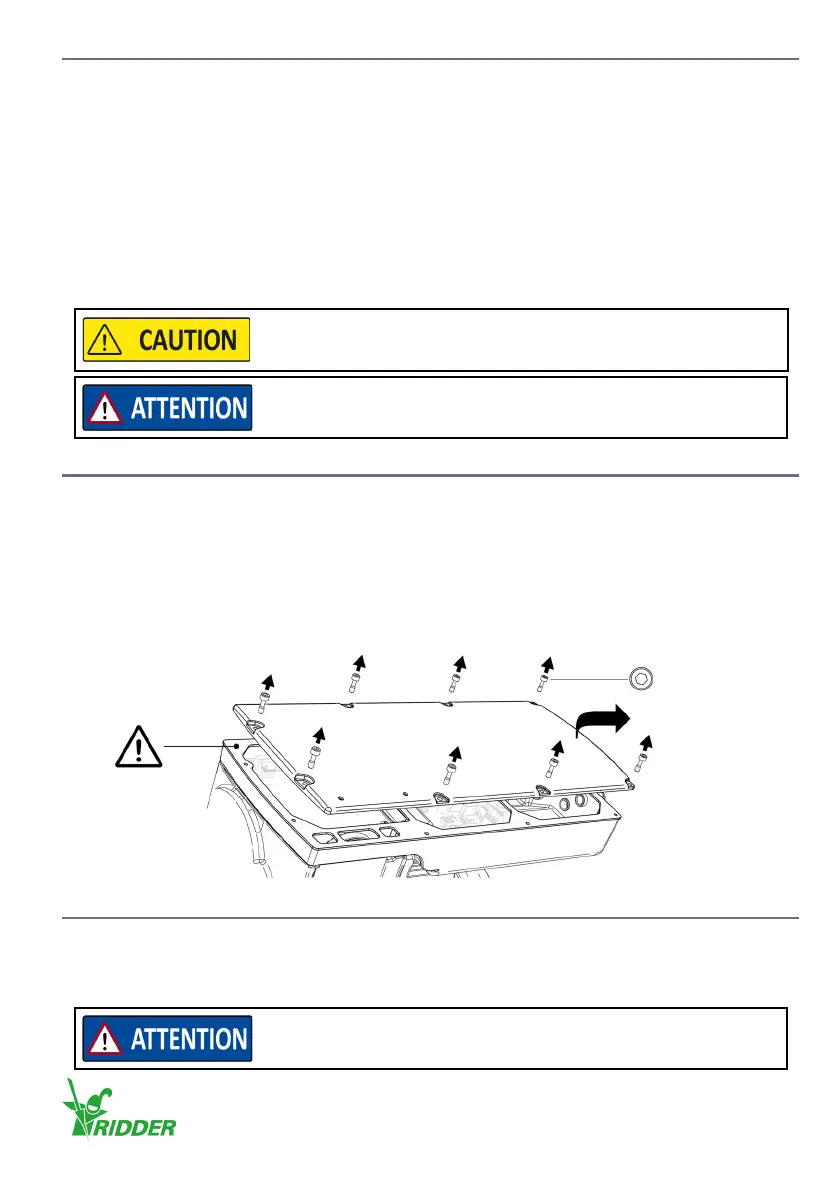
Removal cover
• Remove the bolts (8x) and the cover temporarily to do all necessary work. The gasket usually
stays in its posion.
• Make sure that no damage is caused to the gasket and that it does not become dirty. To prevent
this remove the gasket (carefully) if necessary.
• Install the cover again aer the work! Refer to the end of chapter 7.
5.1 Electrical material
A minimum conductor diameter of 1.5 mm² is applicable to the cables in the wiring diagrams. For
the used components, electrical material and cable lengths the necessary conductor diameter can
be dierent.
Make sure that the drive unit is installed in a stable condion. The
structure must have sucient strength for the applied forces.
Make sure that easy access to the cover of the RLL400 control-unit is
possible for all work.
HEX 4 mm (8x)
Use only applicable components and electrical material.
Always refer to the related informaon and manuals.
Ridder Drive Systems B.V.
T +31 (0)341 416 854 - F +31 (0)341 416 611 - I ridder.com
13