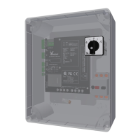
RLL400 control-board (RCB):
5.5 3-phase electric motor (208-600 VAC)
• Make sure that the conguraon (RCB-A or C) on X3 (TRANSFORMER) agrees with the supply
voltage!
• Ridder Drive Systems connects X2 (MOTOR) and X4 (PTC).
• Connect the supply voltage to X1 (MAINS) and PE (protecve earth).
Alarm
§5.11 OPTIONAL
§5.9 OPTIONAL §5.10 OPTIONAL
§5.5/ §5.6/ §5.7
CONTROL BOARD A2 (RCB)
Manual control Posion feedback
Power In
* X3 is not there on RCB-B
Automac Control Transformer configuration Power Out
§5.8
Limit Switch Thermal Protection
Control board A2
A1
(in) (out) (in)
4 x 1.5 mm²
Ridder Drive Systems B.V.
T +31 (0)341 416 854 - F +31 (0)341 416 611 - I ridder.com
16