8. MAINTENANCE INSTRUCTIONS
Inspecon and maintenance work is only permied to approved personnel. If necessary remove
covers to do the work. Refer to chapter 5.
For safe and correct maintenance, read (if necessary) the (applicable) secons of:
• Chapter 2, chapter 6, chapter 7 (§7.1), chapter 9 and chapter 10 (§10.1)
• The product manual of the used Ridder motor-gearbox at ridder.com.
Always put removed covers back aer the work! Refer to the end of chapter 7.
8.1 Maintenance
Maintenance on the RLL400 control-unit is usually not necessary (“maintenance-free”).
It is recommended to do the checks that follow every 6 months:
• Of the correct operaon
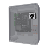
• For a sasfactory view of possible malfuncons and easy access to all LEDs (on the control board
[A2] and optional manual control [MC])
• For error-message indicaons of the blink codes
• Of the mechanical condion (connectors, connecon terminals, fasteners and such).
Contact your supplier if:
• Replacement of parts is necessary
• A problem is found with no soluon. Refer to §9.1 rst.
Refer to the Ridder catalogue or the website at ridder.com for more informaon about spare parts
(or accessories) that are available.
9. SERVICE
If necessary remove covers to do the work. Refer to chapter 5.
For safe and correct servicing, read the (applicable) secons of:
• Chapter 2, chapter 6, chapter 7 (§7.1) and chapter 10 (§10.1).
• The product manual of the used Ridder motor-gearbox at ridder.com.
Always put removed covers back aer the work! Refer to the end of chapter 7.
9.1 Troubleshoong
Troubleshoong is only permied to approved personnel. This secon tells about possible
malfuncons and their soluons. If a malfuncon is not in the list that follows, contact your supplier.
Malfuncon 1 No supply voltage
Observaon 1 The two LEDs D1 and D2 are o (blink code 1.2).
Cause 1 Power supply is externally disconnected.
Soluon 1 Connect power supply.
Ridder Drive Systems B.V.
T +31 (0)341 416 854 - F +31 (0)341 416 611 - I ridder.com
27
 Loading...