Cause 2 No voltage on the control board.
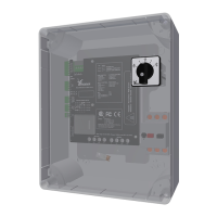
Soluon 2 Measure the supply voltage with a mulmeter on the connecons X1 of the
control board (A2).
Malfuncon 2 Electric motor thermally stopped
Observaon 2 The two LEDs D1 and D2 are on, during and aer a shutdown of the motor for a
minimum of 2 minutes (blink code 1.3).
Cause 1 If the temperature in the electric motor becomes higher than 150 °C the system
will be thermally stopped.
Soluon 1 Set the manual-control switch to posion “0” to erase the error message. When
this occurs again and again or if the error message does not erase, contact your
supplier.
Malfuncon 3 A safety stop of the electric motor occurred.
Observaon 3 The red LED (D2) blinks while the green LED (D1) is on (blink code 1.4).
Cause 1 The duty switch is possibly not disconnected. The electric motor subsequently
operated the safety switch.
Soluon 1 Set the manual-control switch to posion “0” to erase the error message. When
this occurs again and again or if the error message does not erase, contact your
supplier.
Malfuncon 4 Phase failure
Observaon 4 The red LED (D2) blinks while the green LED (D1) is o (blink code 1.5).
Cause 1 A phase failure is detected.
Soluon 1 Make sure that all phases are connected correctly. Make sure that the connecon
terminals have a good connecon.
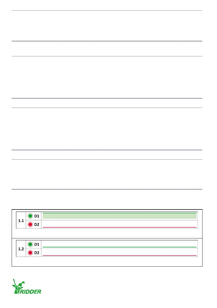
9.2 Blink codes
This secon gives the indicaons and illustraons of the blink codes.
Blink codes
Normal operation: The control unit operates correctly.
No supply voltage: The control unit does not receive a supply voltage.
Ridder Drive Systems B.V.
T +31 (0)341 416 854 - F +31 (0)341 416 611 - I ridder.com
28
 Loading...