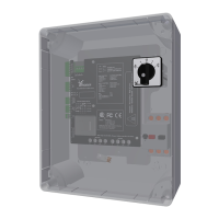
3.3 Applicaon
The LogicLink RLL400 control-unit is installed, as part of a drive unit, on dierent RW motor-
gearboxes. The control-unit is used to control the motor gearboxes in two direcons-of-rotaon.
The RLL400 control-unit (on dierent RW motor-gearboxes) is applicable to:
• Venlaon systems
• Screen systems.
For other (dierent) applicaons, approval from Ridder Drive Systems is necessary.
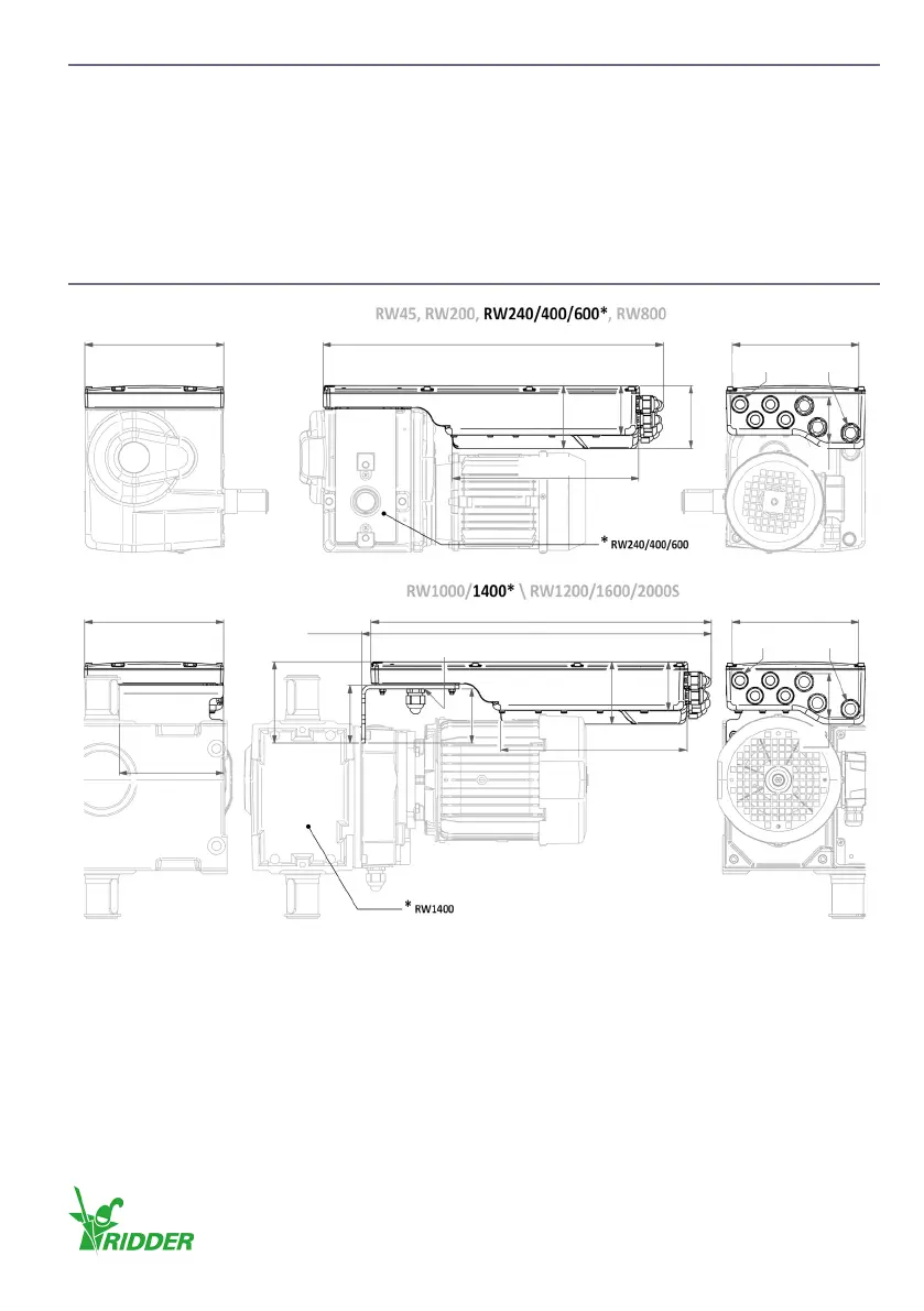
3.4 Dimensions
Note: The dimensions and illustraons are approximate. In this product manual shown illustraons
can be dierent than the components and/or systems.
M16(4x)
200
90
64
90
70
490 182
268.5
M20(3x)
Example:
M16(4x)
200
64
90
70
490 182
268.5
M20(3x)
Example:
M20(1x)
503.5
117
83
78
150
Ridder Drive Systems B.V.
T +31 (0)341 416 854 - F +31 (0)341 416 611 - I ridder.com
9