3. PRODUCT DETAILS
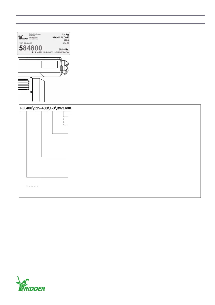
3.1 Idencaon
EXAMPLE
Ê
This product manual is only applicable to:
• Ridder LogicLink RLL400 control-unit
• Serial numbers from 200.900.000
• Item numbers from 500000.
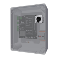
Idencaon is possible from the scker on the locaon shown.
Refer to the explanaon that follows on how to read the informaon.
For more informaon on item numbers and models refer to the
Ridder catalogue or website at ridder.com.
RW1400: RW1000 /1400, RW1200/1600S or RW2000S.
1-5D: 1~ mains voltage, 5-wire electric motor.
Alternatives
1-3: - 1~ mains voltage, 3-wire electric motor.
- 3~ mains voltage.
3: 3~ mains voltage.
Alternatives
115-400: Mains voltage 115 V/230 V (1~) or 208 V/400 V (3~).
RLL400: General designaon Ridder RLL400 control units.
1~ = 1-phase
= No symbol in idencaon. RW45, RW200, RW240/400/600 or RW800 motor gearbox.
( - ): RW45, RW200, RW240/400/600 or RW800.
3~ = 3-phase
400: Mains voltage 400 V (3~).
440-600: Mains voltage 440 V, 480 V or 600 V (3~).
Ridder Drive Systems B.V.
T +31 (0)341 416 854 - F +31 (0)341 416 611 - I ridder.com
7