4-A
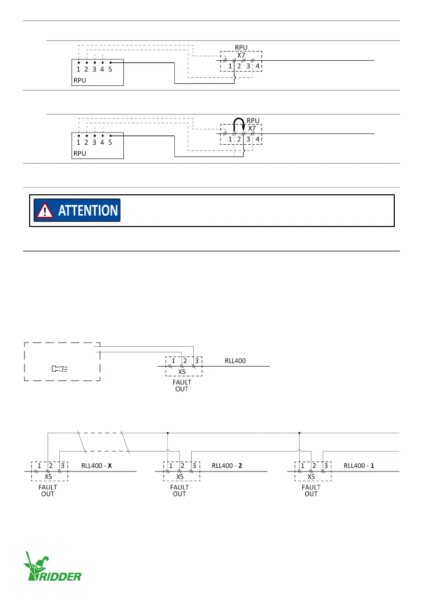
The reference-input connecon (connecon 2 of X7) is CORRECT. Go to step 5.
Control board A2
4-B
The reference-input connecon (connecon 2 of X7) is NOT CORRECT.
Interchange the connecons 2 and 3. Go to step 5.
Control board A2
5
The RPU is prepared to set the end posions.
Refer to the RPU product manual at ridder.com.
5.11 OPTIONAL - Alarm (AL)
The RLL400 control-board (A2) has an output for a fault contact (X5) that opens when a random
fault occurs. You can include this fault contact in an alarm circuit.
You can connect one or more control units to an alarm circuit.
Connecng - One RLL400 control-unit
Obey the diagram that follows to connect one control unit.
Connecng - Two or more RLL400 control-units
Obey the diagram that follows to connect the fault contacts (X5) to two or more control units.
It is only permied to connect the RPU reference-input to X7 of the
control board (A2). Do NOT connect it to the RSU/RLS.
Refer to §3.5 (Technical specicaons) of X7 and X9.
Control board A2
Alarm
AL
Control board A2 Control board A2 Control board A2
Alarm (AL)
Ridder Drive Systems B.V.
T +31 (0)341 416 854 - F +31 (0)341 416 611 - I ridder.com
20