6.3 Operaon
This secon tells about the operang funcons of the RLL400 control-unit connected to a Ridder
manual control (MC) (277950) and an automac control-system (ACS). Always refer to the related
informaon and manuals (ACS and MC).
LED - Red LED - Green
Before you use the manual control, make sure that the green LED on the manual control (and D1 on
control board A2) is on.
Blink code 1.1 gives the indicaon: No malfuncons, the control unit operates correctly.
Refer to §9.2.
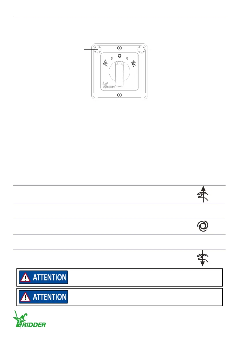
The switch with ve posions has the four funcons that follow:
1. The system is manually controlled in direcon A or B. The system is controlled independently
also if there is an automac 24 V AC/DC control signal (ACS).
2. The system is put in Automac mode.
The system is controlled if there is an automac 24 V AC/DC control signal (ACS).
3. The system is manually stopped if the switch is set to posion “0”.
4. The error messages are erased if the switch is set to posion “0”.
Funcon Descripon
1
Direcon A
3
4
The manual control does not control the electric motor.
Posion to erase error messages aer a malfuncon.
0
2
Automatic mode, the control unit operates when it receives
external control from an ACS.
3
4
The manual control does not control the electric motor.
Posion to erase error messages aer a malfuncon.
0
1
Direcon B
Control signals from an automac control system (ACS) are only
processed if the manual control (MC) is in Automac mode.
Automac mode is only in operaon if there is an automac control
signal (ACS).
Ridder Drive Systems B.V.
T +31 (0)341 416 854 - F +31 (0)341 416 611 - I ridder.com
22
 Loading...